
Computer Hardware User Manual

102 SKA4 Baseboard Product Guide
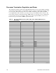
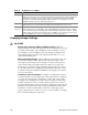
Processor Termination, Regulation, and Power
The termination circuitry required by the Intel Pentium III Xeon processor bus (AGTL+) signaling
environment and the circuitry to set the AGTL+ reference voltage, are implemented directly on the
processor cards.
The baseboard provides 1.5 V AGTL+ termination power (VTT), and VRM
8.3-compliant DC-to-DC converters to provide processor power (VCCP) at each connector.
The
baseboard provides three embedded and three VRM sockets to power the processors, which derive
power from the +5 V and 12 V supplies.
Each processor has a separate VRM to power its core;
however, two processors share a VRM to power their cache.
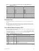
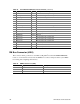
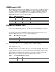
Table 55. Processor VRM Connectors (J2A2, J2B1, J2C1): Add-in VRM Connector
Pin Listing
Pin Signal Type*
A1 P5VIN1 POWER
A2 P5VIN2 POWER
A3 P5VIN3 POWER
A4 P12VIN1 POWER
A5 P12VIN3 POWER
A6 P1SHARE
A7 VID0 OUT
A8 VID2 OUT
A9 VID4 OUT
A10 VCCP1 POWER
A11 VSS1 POWER
A12 VCCP2 POWER
A13 VSS2 POWER
A14 VCCP3 POWER
A15 VSS3 POWER
A16 VCCP4 POWER
A17 VSS4 POWER
A18 VCCP5 POWER
A19 VSS5 POWER
A20 VCCP6 POWER
B1 P5VIN4 POWER
B2 P5VIN5 POWER
B3 P5VIN6 POWER
B4 P12VIN2 POWER
B5 RES
B6 OUTEN OUT
B7 VID1 OUT
B8 VID3 OUT
B9 PWRGOOD
continued