Application Note Building Fault-tolerant SS7 Systems Using the Intel® NetStructure™ SIU520 SS7 Signaling Gateway Intel in Communications
Building Fault-tolerant SS7 Systems Using the Intel® NetStructure™ SIU520 SS7 Signaling Gateway Application Note Table of Contents Abstract 1 Introduction 1 Overview of SIU Operation 2 Circuit-switched API Operation 2 Transaction-based API Operation 3 Management Interface 3 Potential Points of Failure 3 Failure of SS7 Links 4 Failure of Routes 5 Failure of Power Supply 6 Failure of Signaling Interface Unit Routing Architectures of a Dual-resilient SIU System Dual SIU architecture for Ci
Application Note Building Fault-tolerant SS7 Systems Using the Intel® NetStructure™ SIU520 SS7 Signaling Gateway Table of Figures Figure 1 Structure of the Intel® NetStructure™ SIU520 SS7 Signaling Gateway 2 Figure 2 Integrating the SIU520 3 Figure 3 SIU Connected to Adjacent Node with Two Links in Link Set 4 Figure 4 SIU520 Connected to Mated STP Pair Providing Route Resiliency 5 Figure 5 Dual SIU Architecture 6 Figure 6 Transmit Routing to a Single Destination 7 Figure 7 Dual-resilient
Building Fault-tolerant SS7 Systems Using the Intel® NetStructure™ SIU520 SS7 Signaling Gateway Application Note Abstract In order to achieve five-nines (99.999%) reliability and a high degree of fault tolerance in an SS7 environment using Intel® NetStructure™ SIU520 signaling gateways, an SS7 end point spread over two signaling interface units (SIUs) and multiple application servers can be configured and deployed.
Application Note Building Fault-tolerant SS7 Systems Using the Intel® NetStructure™ SIU520 SS7 Signaling Gateway Application #1 Application #0 Application #N Ethernet API Layer/Ethernet Driver MAP or INAP or IS41 ISUP TCAP Configuration and Management TUP SCCP MTP Levels 1-3 SIU 520 Figure 1.
Building Fault-tolerant SS7 Systems Using the Intel® NetStructure™ SIU520 SS7 Signaling Gateway Application Note } CT Application Platform } SIU520 SS7 Information CT Application Platform E-1 or T-1 Trunks, Voice Circuits Only E-1 or T-1 Trunks with SS7 Channel and Voice Circuits Ethernet Figure 2.
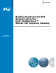
Application Note Building Fault-tolerant SS7 Systems Using the Intel® NetStructure™ SIU520 SS7 Signaling Gateway A) Load sharing between link 0 and link 1 under normal conditions Link id 0, slc 0 SIU520 Link id 1, slc 1 Point Code 0x100 SSP/SCP Point Code 0x200 Link Set id 0 B) Traffic sent over link 1 under failure of link 0 SIU520 Point Code 0x100 SSP/SCP Point Code 0x200 Figure 3.
Building Fault-tolerant SS7 Systems Using the Intel® NetStructure™ SIU520 SS7 Signaling Gateway Application Note A) Load sharing between link set 0 and link set 1 under normal Link Set id 0 STPA Link id , slc 0 0 Point Code 0x200 SIU520 Link id Point Code 0x100 1, slc SSP/SCP 0 STPB Link Set id 1 Point Code 0x400 Point Code 0x300 B) Traffic sent over link set 1 under failure of STP Link Set id 0 Link id 0, slc 0 SSP/SCP SIU520 Link id Point Code 0x100 1, slc 0 STPB Link Set id 1 Point
Application Note Building Fault-tolerant SS7 Systems Using the Intel® NetStructure™ SIU520 SS7 Signaling Gateway Application Ethernet Ethernet SIUA SIUB API Layer/Ethernet Driver API Layer/Ethernet Driver Distributed Layer 4 Management MAP or INAP or IS41 TCAP ISUP TUP MAP or INAP or IS41 ISUP TCAP TUP SCCP SCCP Distributed MTP3 Management MTP Levels 1-3 SS7 SS7 MTP Levels 1-3 Link Set Figure 5.
Building Fault-tolerant SS7 Systems Using the Intel® NetStructure™ SIU520 SS7 Signaling Gateway Application Note A) Normal routing case Single Point Code Inter-SIU Link Set SIUA F-Links Link Set id 0 SSP/SCP SIUB Link Set id 1 B) Routing under network link failure Single Point Code Inter-SIU Link Set SIUA Link Set id 0 SSP/SCP SIUB Link Set id 1 Figure 6.
Application Note Building Fault-tolerant SS7 Systems Using the Intel® NetStructure™ SIU520 SS7 Signaling Gateway Single Point Code Link Set id 1 Inter-SIU Link Set STPA SIUA Link Set id 0 SSP/SCP A-Links SIUB STPB Link Set id 2 Figure 7. Dual-resilient SIUs Connected to a Mated STP Pair in a Straight Link Configuration Single Point Code Link Set id 1 Inter-SIU Link Set STPA SIUA Link Set id 0 SSP/SCP SIUB STPB Link Set id 2 Figure 8.
Building Fault-tolerant SS7 Systems Using the Intel® NetStructure™ SIU520 SS7 Signaling Gateway Application Note A) Normal routing case (both network link sets available) Single Point Code Link Set id 1 Inter-SIU Link Set SSP/SCP STPA SIUA A-Links Link Set id 0 SIUB C-Links STPB Link Set id 2 B) Routing under failure of network link set between SIUA and adjacent STP Single Point Code Link Set id 1 Inter-SIU Link Set SSP/SCP SIUA A-Links Link Set id 0 SIUB C-Links Link Set id 2 Transmit Traffi
Application Note Building Fault-tolerant SS7 Systems Using the Intel® NetStructure™ SIU520 SS7 Signaling Gateway MTP1-3 Circuit Group 0 [Active] Circuit Group 1 [Inactive] SS 7 SIUA Adjacent Signaling Point Inter-SIU SS7 Link Set Application SS 7 TCP/IP Ethernet Circuit Group 0 [Inactive] Circuit Group 1 [Active] SIUB MTP1-3 Transmit traffic for circuits active on SIUA Received traffic for circuits active on SIUA Figure 10.
Building Fault-tolerant SS7 Systems Using the Intel® NetStructure™ SIU520 SS7 Signaling Gateway Application Note MTP1-3 Circuit Group 0 [Active] Circuit Group 1 [Inactive] SIUA Adjacent Signaling Point Inter-SIU SS7 Link Set Application SS 7 TCP/IP Ethernet Circuit Group 0 [Inactive] Circuit Group 1 [Active] MTP1-3 SIUB Transmit traffic for circuits active on SIUA Received traffic for circuits active on SIUA Figure 11.
Application Note Building Fault-tolerant SS7 Systems Using the Intel® NetStructure™ SIU520 SS7 Signaling Gateway SIUA Adjacent Signaling Point SS 7 Application TCP/IP Ethernet Circuit Group 0 [Active] Circuit Group 1 [Active] MTP1-3 SIUB Figure 12. Routing Following Failure of SIUA The circuit group control will then appear as shown in Figure 12. The user application software should reset all idle circuits following a transfer, and reset all remaining circuits as they become idle.
Building Fault-tolerant SS7 Systems Using the Intel® NetStructure™ SIU520 SS7 Signaling Gateway Application Note A) Dual-resilient SIUs running SS7 protocol stack to TCAP Host 0 B) Dual-resilient SIUs running SS7 protocol stack up to SCCP Host N Host 0 Host N TC User ... TC User TC User TC User ... TCAP TCAP DTC DTC Ethernet SIUB SIUA Ethernet TCAP TCAP SCCP SCCP MTP MTP SIUB SIUA DTS DTS SCCP SCCP MTP MTP Figure 13.
Application Note Building Fault-tolerant SS7 Systems Using the Intel® NetStructure™ SIU520 SS7 Signaling Gateway SIUA Ethernet TCAP instance = 0 SCCP SS7 MTP Inter-chassis communication (RSI) SS7 Application SS7 Adjacent Signaling Point MTP SCCP TCAP instance = 1 SIUB Transmit message for transaction handled by TCAP B Message received for transaction handled by TCAP B Figure 14.
Building Fault-tolerant SS7 Systems Using the Intel® NetStructure™ SIU520 SS7 Signaling Gateway Application Note Application Host Subn etwor Subne k1 twork twor Subne Application Host Subn 2 k2 etwo SIU520 rk 1 Figure 15. Dual LAN Operation on the SIU520 Failure of IP Subnetwork Problem — Should one subnetwork go down due to a network component failure, the hosts connected to the SIU over the other subnetworks will remain active and attempt to preserve half of the total system capacity.
Application Note Building Fault-tolerant SS7 Systems Using the Intel® NetStructure™ SIU520 SS7 Signaling Gateway Host 0 Host 1 Host 2 Application Application Application Host 3 Application Ethernet SIU520 TCAP SCCP SS7 MTP Figure 16.
Building Fault-tolerant SS7 Systems Using the Intel® NetStructure™ SIU520 SS7 Signaling Gateway Application Note Signaling Card PCM Trunk #0 PCM Trunk #1 SS7 Network E-1 Trunk Containing SS7 Signaling Only SIUA PCM Trunk #2 PCM Trunk #3 Signaling Card Inter-SIU SS7 Link Set E-1 Trunk PCM Trunk #0 SS7 Network PCM Trunk #1 E-1 Trunk Containing SS7 Signaling Only SIUB PCM Trunk #2 PCM Trunk #3 Figure 17.
Application Note Building Fault-tolerant SS7 Systems Using the Intel® NetStructure™ SIU520 SS7 Signaling Gateway Signaling Card SS7 Network PCM Trunk #0 E-1 or T-1 Trunk Containing SS7 Signaling and Voice Circuits PCM Trunk #1 SIUA V.11 Port #A V.11 Port #B Inter-SIU SS7 Link Set Voice Processing Platform Signaling Card SS7 Network PCM Trunk #0 E-1 or T-1 Trunk Containing SS7 Signaling and Voice Circuits PCM Trunk #1 SIUB V.11 Port #A V.11 Port #B Figure 18. Inter-SIU Link Set over V.
Building Fault-tolerant SS7 Systems Using the Intel® NetStructure™ SIU520 SS7 Signaling Gateway Application Note Single Point Code Inter-SIU Link Set Link id 1, slc 0 SIUA Link Set id 0 SSP/SCP SIUB Link id 1, slc 1 Link_id 0, slc 0 Point Code 200 Point Code 100 Link Set id 1 Figure 19. Example Configuration to an Adjacent SSP/SCP using the MTP_LINK command, assigning incrementing and values as normal.
Application Note Building Fault-tolerant SS7 Systems Using the Intel® NetStructure™ SIU520 SS7 Signaling Gateway Single Point Code Point Code 400 Link Set id 1 Inter-SIU Link Set link_id 1, slc 0 STPA SIUA Link Set id 0 SSP/SCP SIUB Point Code 600 Point Code 300 link _id 1, s lc 0 Link Set id 1 STPB Point Code 500 Figure 20.
Building Fault-tolerant SS7 Systems Using the Intel® NetStructure™ SIU520 SS7 Signaling Gateway Application Note Communicating with Both SIUA and SIUB The user application exchanges information with the SIU via API messages (MSG). In a dual SIU environment, each time the user application sends a message to the SIU, this should be directed to either SIUA or SIUB using a library function GCT_set_instance.
Application Note Building Fault-tolerant SS7 Systems Using the Intel® NetStructure™ SIU520 SS7 Signaling Gateway conc_id on the host (conc_id is set when the RSI link was started, optionally by rsicmd). This message will only be received by the application if the RSI link is configured with the conc_id set to the application’s module ID.
Building Fault-tolerant SS7 Systems Using the Intel® NetStructure™ SIU520 SS7 Signaling Gateway Application Note Recovery of the Failed Unit The host application is informed of recovery of the communication to the SIU with the same method used for notification of the failure. The RSI_MSG_LINK_ STATUS message in this case contains a status value of 1 (link to SIU recovered).
Application Note Building Fault-tolerant SS7 Systems Using the Intel® NetStructure™ SIU520 SS7 Signaling Gateway Appendix A: Frequently Asked Questions Q: How can I tell if an SIU fails? Q: Do I need to activate circuit groups on a single SIU configuration? A: The status of the communication between the host and the SIU is indicated by RSI_MSG_STATUS messages. A: No.
To learn more, visit our site on the World Wide Web at http://www.intel.com. 1515 Route Ten Parsippany, NJ 07054 Phone: 1-973-993-3000 INFORMATION IN THIS DOCUMENT IS PROVIDED IN CONNECTION WITH INTEL® PRODUCTS. NO LICENSE, EXPRESS OR IMPLIED, BY ESTOPPEL OR OTHERWISE, TO ANY INTELLECTUAL PROPERTY RIGHTS IS GRANTED BY THIS DOCUMENT, EXCEPT AS PROVIDED IN INTEL'S TERMS AND CONDITIONS OF SALES FOR SUCH PRODUCTS.