SG-80 Series (SG-80, SG-81) Intel Pentium 4 System Board Socket 775 User’s Manual Rev. 1.
Copyright and Warranty Notice The information in this document is subject to change without notice and does not represent a commitment on part of the vendor, who assumes no liability or responsibility for any errors that may appear in this manual. No warranty or representation, either expressed or implied, is made with respect to the quality, accuracy or fitness for any particular part of this document.
Table of Contents Chapter 1. 1.1. 1.2. 1.3. 1.4. Chapter 2. 2.1. 2.2. 2.3. Chapter 3. 3.1. Introduction .................................................... 1-1 Features & Specifications....................................................... 1-1 Layout Diagram (SG-80)........................................................ 1-3 Layout Diagram (SG-81)........................................................ 1-4 Jumpers & Connectors Description........................................ 1-5 Hardware Setup.....
3.2. Chapter 4. 4.1. Using BIOS ............................................................................ 3-4 3.2.1. Standard CMOS Features ......................................... 3-4 3.2.2. Advanced BIOS Features ......................................... 3-7 3.2.3. Advanced Chipset Features .................................... 3-10 3.2.4. Integrated Peripherals ............................................. 3-14 3.2.5. Power Management Setup ...................................... 3-18 3.2.6.
Introduction 1-1 Chapter 1. Introduction 1.1. Features & Specifications CPU • • Designed for Intel® 90nm Pentium 4/Celeron D LGA775 Processors with 800/533 MHz FSB Supports Intel Hyper-Threading Technology Chipset • SIS 661FX/ 964 (L) Memory • • • Two 184-pin DIMM sockets Supports DDR400 non-ECC un-buffered memory Supports maximum memory capacity up to 2GB Graphic • Integrated SIS Mirage Graphics GPU high performance 256-bit 3D engine and 2D Accelerator SATA 150 (Option) • • Serial ATA 1.
1-2 Chapter 1 Back Panel I/O • • • • 1x PS/2 Keyboard, 1x PS/2 Mouse 1x Serial Port, 1x Parallel Port, 1x VGA connector 4x USB 2.0, 1x RJ-45 LAN Connector 1x Audio connectors (Line-out, Line-in, MIC-in) Miscellaneous • Micro ATX form factor (244mm x 244mm) Product List Model Chipset Features SG-80 SIS 661FX + 964 10/100 LAN + SATA SG-81 SIS 661FX + 964L 10/100 LAN All brand names and trademarks are the property of their respective owners.
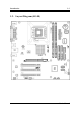
Introduction 1-3 1.2.
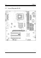
1-4 1.3.
Introduction 1-5 1.4.
1-6 SG-80 Series Chapter 1
Hardware Setup Chapter 2. 2-1 Hardware Setup 2.1. CPU Socket This server board provides one 775-pin Zero Insertion Force (ZIF) socket to install the Intel Pentium 4 CPU.
2-2 Chapter 2 2.2. System Memory This system board provides two 184-pin DDR DIMM slots for un-buffered and non-ECC modules with memory size expansible up to 2GB (DDR400).
Hardware Setup 2-3 2.3. Connectors, Headers, and Switches All the connectors, headers and switches mentioned here are depending on your system configuration. Some features you may (or may not) have to connect or to configure depending on the peripherals you have connected. WARNING: Always power off the computer and unplug the AC power cord before adding or removing any peripheral or component. Failing to so may cause severe damage to your system board and/or peripherals.
2-4 2.3.2. Chapter 2 FAN Connectors (CPUFAN, SYSFAN, PWRFAN) These connectors each provide power to the cooling fans installed in your system. • CPUFAN: Power connector for CPU cooling fan • SYSFAN, PWRFAN: Power connector for System and Power Fan WARNING: These fan connectors are not jumpers. DO NOT place jumper caps on these connectors.
Hardware Setup 2.3.3. 2-5 CMOS Memory Clearing Header (CCMOS) This header uses a jumper cap to clear the CMOS memory. • Pin 2-3 shorted (default): Normal operation. • Pin 1-2 shorted: Clear CMOS memory. ATTENTION: Turn the system power off first (including the +5V standby power) before clearing the CMOS memory. Failing to do so may cause your system to work abnormally or malfunction.
2-6 2.3.4. Chapter 2 Front Panel Switches & Indicators Connection Headers (PANEL1) These headers are used for connecting switches and LED indicators on the chassis front panel. The mark “+” align to the pin in the figure below stands for positive polarity for the LED connection.
Hardware Setup 2.3.5. 2-7 Additional USB Port Connection Header (USB3, USB4) These headers each provide 2 additional USB 2.0 ports connection through an USB cable designed for USB 2.0 specifications.
2-8 2.3.6. Chapter 2 Front Panel Audio Connection Header (FPIO-AUDIO1) This header provides the connection to audio connector at front panel. • To use the audio connector at front panel, remove all the jumpers on this header, and then connect to front panel by the extension cable provided with the chassis. • To use the audio connector at rear panel, disconnect the extension cable, attach the jumpers back at pin 5-6, and pin 9-10 (default setting).
Hardware Setup 2.3.7. 2-9 Accelerated Graphics Port Slot (AGP1) This slot supports an optional AGP graphics card up to AGP 8X/4X mode. ATTENTION: This motherboard does not support 3.3V AGP cards. Use only 1.5V or 0.8V AGP cards.
2-10 2.3.8. Chapter 2 Internal Audio Source Connectors (CD1, AUX1) These connectors connect to the audio output of internal CD-ROM drive or add-on card.
Hardware Setup 2.3.9. 2-11 Floppy Disk Drive Connector (FDC) This connector supports two standard floppy disk drives via a 34-pin 34-conductor ribbon cable. Connecting the Floppy Disk Drive Cable: 1. Install one end of the ribbon cable into the FDC connector. The colored edge of the ribbon cable should be aligned with pin-1 of FDC connector. 2. Install the other end(s) of ribbon cable into the disk drive connector(s).
2-12 2.3.10. Chapter 2 IDE Disk Drive Connectors (IDE1, IDE2) These IDE ports each connects up to two IDE drives at Ultra ATA/100 mode by one 40-pin, 80-conductor, and 3-connector Ultra ATA/66 ribbon cables. Connect the single end (blue connector) at the longer length of ribbon cable to the IDE port on system board, and the other two ends (gray and black connector) at the shorter length of the ribbon cable to the connectors on hard drives.
Hardware Setup 2.3.11. 2-13 Serial ATA connectors (SATA1, SATA2) These connectors are provided to attach one Serial ATA device at each channel via Serial ATA cable.
2-14 2.3.12. Chapter 2 External I/O Panel • Mouse: PS/2 mouse connector. • Keyboard: PS/2 keyboard connector. • LPT1: Parallel port connector. • COM1: Serial port connector. • VGA1: Monitor signal connector. • USB1/USB2: USB 2.0 connectors. • LAN1:10/100Mbps LAN connectors. • AUDIO: Mic In: Connects to the plug from external microphone. Line In: Connects to the line out from external audio sources. Line Out: Connects to the front left and front right channel in the 5.
BIOS Setup Chapter 3. 3-1 BIOS Setup 3.1. About the Setup Utility The computer uses the latest Award BIOS with support for Windows Plug and Play. The CMOS chip on the motherboard contains the ROM setup instructions for configuring the motherboard BIOS. The BIOS (Basic Input and Output System) Setup Utility displays the system’s configuration status and provides you with options to set system parameters.
3-2 Chapter 3 3.1.2. Entering the Setup Utility When you power on the system, BIOS enters the Power-On Self Test (POST) routines. POST is a series of built-in diagnostics performed by the BIOS.
BIOS Setup 3.1.3. 3-3 Updating the BIOS You can download and install updated BIOS for this motherboard from the manufacturer’s Web site. New BIOS provides support for new peripherals, improvements in performance, or fixes for known bugs. Install new BIOS as follows: 1. If your motherboard has a BIOS protection jumper, change the setting to allow BIOS flashing. 2. If your motherboard has an item called Firmware Write Protect in Advanced BIOS features, disable it.
3-4 Chapter 3 3.2. Using BIOS When you start the Setup Utility, the main menu appears. The main menu of the Setup Utility displays a list of the options that are available. A highlight indicates which option is currently selected. Use the cursor arrow keys to move the highlight to other options. When an option is highlighted, execute the option by pressing . Some options lead to pop-up dialog boxes that prompt you to verify that you wish to execute that option.
BIOS Setup 3-5 IDE Devices (None) Your computer has two IDE channels (Primary and Secondary) and each channel can be installed with one or two devices (Master and Slave). Use these items to configure each device on the IDE channel. This motherboard features two SATA connectors supporting two SATA drives. SATA refers to Serial ATA (Advanced Technology Attachment), the standard interface for the IDE hard drives which are currently used in most PCs.
3-6 Chapter 3 Refer to your drive’s documentation or look on the drive casing if you need to obtain this information. If no device is installed, change the value to None. NOTE: Before attempting to configure a hard disk drive, ensure that you have the configuration information supplied by the manufacturer of your hard drive. Incorrect settings can result in your system not recognizing the installed hard disk.
BIOS Setup 3.2.2. 3-7 Advanced BIOS Features This option defines advanced information about your system. CPU Feature Scroll to this item and press to view the following screen: Users please note that this function is only available for Prescott CPUs.
3-8 Chapter 3 Thermal Management This item displays CPU’s temperature and enables you to set a safe temperature to Prescott CPU. TM2 Bus Ratio This item represents the frequency (bus ratio) of the throttled performance state that will be initiated when the on-die sensor goes from not hot to hot). TM2 Bus VID This item represents the voltage of the throttled performance state that will be initiated when the on-die sensor goes from not hot to hot.
BIOS Setup 3-9 CPU L3 Cache (Enabled) This item is only available when processors support L3. Some high-end processors support L3. If the CPU do support L3, you may set this item to enable or disable. Leave this item at the default value for better performance. Hyper-Threading Technology (Enabled) This item is only available when the chipset supports Hyper-Threading and you are using a Hyper-Threading CPU.
3-10 Chapter 3 ATA 66/100 IDE Cable Msg. (Enabled) This item enables or disables the display of the ATA 66/100 Cable MSG. Security Option (Setup) If you have installed password protection, this item defines if the password is required at system start up, or if it is only required when a user tries to enter the Setup Utility. Small Logo(EPA) Show This item determines to show the EPA logo when booting. 3.2.3. Advanced Chipset Features These items define critical timing parameters of the motherboard.
BIOS Setup 3-11 DRAM Clock/Timing Control: Scroll to this item and press to view the following screen: DRAM Timing Control Enables you to select the CAS latency time in HCLKs of 2, 2.5, or 3. The value is set at the factory depending on the DRAM installed. Do not change the values in this field unless you change specifications of the installed DRAM or the installed CPU.
3-12 Chapter 3 RAS to CAS Delay (tRCD): This is the amount of time a CAS is performed after a RAS. The lower the better, but some DRAM does not support low figures. Press to return to the Advanced Chipset Features page. AGP & P2P Bridge Control Scroll to this item and press to view the following screen: AGP Aperture Size This setting controls just how much system RAM can be allocated to AGP for video purposes.
BIOS Setup 3-13 AGP Data Rate (Auto) This item allows users to set the AGP Data Rate by, Auto, 1X, 2X, 4X, or 8X, depending on what speed the AGP card supports. Press to return to the Advanced Chipset Features page. OnChip AGP Control Scroll to this item and press to view the following screen: VGA Share Memory Size (32M) This item allows you to select the shared memory size for VGA usage. Press to return to the Advanced Chipset Features screen.
3-14 Chapter 3 3.2.4. Integrated Peripherals These options display items that define the operation of peripheral components on the system’s input/output ports.
BIOS Setup 3-15 Internal PCI/IDE (Both) Use these items to enable or disable the internal PCI IDE channels that are integrated on the mainboard. IDE DMA Transfer Access (Enabled) This item allows you to enabled the transfer access of the IDE DMA. IDE Burst Mode (Enabled) This option, when enabled will instruct the system to send every write transaction to the write buffer. Burstable transactions then burst onto the PCI bus and nonburstable transactions do not.
3-16 Chapter 3 OnChip PCI Device Scroll to this item and press to view the following screen: OnChip USB Controller (Enabled) Enable this item if you plan to use the Universal Serial Bus ports on this mainboard. OnChip AC97 Controller (Enabled) Enables or disables the onboard AC97 audio function. Disable this item if you are going to install a PCI audio add-on card. OnChip LAN Controller (Enabled) Enables and disables the onboard LAN chip.
BIOS Setup 3-17 Press to return to the Integrated Peripherals screen. Onboard SuperIO Device: Scroll to this item and press to view the following screen: Onboard FDC Controller (Enabled) This option enables the onboard floppy disk drive controller. Onboard Serial Port 1 (3F8/IRQ4) This option is used to assign the I/O address and interrupt request (IRQ) for onboard serial port1 (COM1).
3-18 Chapter 3 ECP Mode Use DMA (3) When the onboard parallel port is set to ECP mode, the parallel port can use DMA3 or DMA1. Press to return to the Integrated Peripherals screen. Onboard 1394 Device (Enabled) Enables and disables the onboard IEEE 1394 controller. Init Display First (PCI Slot) Use this item to specify whether your graphics adapter is installed in one of the PCI slots or is integrated on the motherboard. 3.2.5.
BIOS Setup 3-19 Resume by USB from S3 (Disabled) When set to Enabled, the system power will resume the system from a power saving mode if there is any USB port activity. Power On by PS2 Keyboard (Hot Key) This option enables you to allow the keyboard activity to awaken the system from power saving mode. Power On by PS2 Mouse (Disabled) This option enables you to allow the mouse activity to awaken the system from power saving mode.
3-20 Chapter 3 [Power Off]: When power returns after an AC power failure, the system’s power remains off. You must press the Power button to power-on the system. [Power On]: When power returns after an AC power failure, the system’s power will be powered on automatically. [Last State]: When power returns after an AC power failure, the system will return to the state where you left off before power failure occurs.
BIOS Setup 3-21 If you cannot get a legacy ISA (Industry Standard Architecture) expansion card to work properly, you might be able to solve the problem by changing this item to Manual, and then opening up the IRQ Resources submenu. In the IRQ Resources submenu, if you assign an IRQ to Legacy ISA, then that Interrupt Request Line is reserved for a legacy ISA expansion card. Press to close the IRQ Resources submenu.
3-22 Chapter 3 PIRQ_0 Use IRQ No. ~ PIRQ_7 Use IRQ No. [Auto] This item specifies the IRQ number manually or automatically for the devices installed on PCI slots. 3.2.7. PC Health Status On motherboards that support hardware monitoring, this item lets you monitor the parameters for critical voltages, critical temperatures, and fan speeds. CPU Shutdown Temperature (Disabled) This item sets the temperature that would shutdown the system automatically in order to prevent system overheats.
BIOS Setup 3.2.8. 3-23 Frequency Control This item enables you to set the clock speed and system bus for your system. The clock speed and system bus are determined by the kind of processor you have installed in your system. Auto Detect DIMM/PCI Clk (Enabled) When this item is enabled, BIOS will disable the clock signal of free DIMM/PCI slots. Spread Spectrum (Enabled) If you enable spread spectrum, it can significantly reduce the EMI (Electro-Magnetic Interference) generated by the system.
3-24 Chapter 3 Press and then to install the defaults. Press and then to not install the defaults. The fail-safe defaults place no great demands on the system and are generally stable. If your system is not functioning correctly, try installing the fail-safe defaults as a first step in getting your system working properly again. If you only want to install fail-safe defaults for a specific option, select and display that option, and then press . 3.2.10.
BIOS Setup 3.2.12. 3-25 Save & Exit Setup Option Highlight this item and press to save the changes that you have made in the Setup Utility and exit the Setup Utility. When the Save and Exit dialog box appears, press to save and exit, or press to return to the main menu: 3.2.13. Exit Without Saving Highlight this item and press to discard any changes that you have made in the Setup Utility and exit the Setup Utility.
3-26 SG-80 Series Chapter 3
Driver Installation Chapter 4. 4-1 Driver Installation All the necessary drivers are included within the Drivers & Utilities CD that came packaged with your board. The display shown in the following figure should appear after inserting this CD into your CD-ROM drive, if not, enter [My Computer] [CD-ROM] Drive double click [autorun.exe]. Please follow the on-screen instruction.
4-2 Chapter 4 4.1. Setup Items • Drivers Install the drivers for Windows Operating System. • Manual View the user’s manual in PDF file. • Utility Click to enter the sub-screen for installing software like Acrobat Reader, Award Flash, DirectX, and LoFormat utility. • Browse CD Browse the contents of this CD-ROM. • Close Exit the CD setup Items Menu.
How to Get Technical Support A-1 Appendix A. How to Get Technical Support (From our website) http://www.abit.com.tw (In North America) http://www.abit-usa.com (In Europe) http://www.abit.nl Thank you for choosing ABIT products. ABIT sells all our products through distributors, resellers and system integrators; we have no direct sales to end-users.
A-2 Appendix A alt.comp.periphs.mainboard.abit comp.sys.ibm.pc.hardware.chips alt.comp.hardware.overclocking alt.comp.hardware.homebuilt alt.comp.hardware.pc-homebuilt 5. Ask your reseller. Your ABIT authorized distributor should be able to provide the fastest solution to your technical problem. We sell our products through distributors who sell to resellers and stores.
How to Get Technical Support North America and South America RMA Center UK and Ireland Germany and Benelux (Belgium, Netherlands, Luxembourg), France, Italy, Spain, Portugal, Greece, Denmark, Norway, Sweden, Finland, and Switzerland Austria, Czech, Romania, Bulgaria, Slovakia, Croatia, Bosnia, Serbia, and Macedonia Shanghai Russia and CIS Poland Japan Taiwan Head Office (Serving all other territories not listed above. Taiwan is 8+ GMT time, and may have different holiday calendar from yours.
A-4 Appendix A Technical Support Form Company Name: Phone Number: Contact Person: Fax Number: E-mail Address: Model * Motherboard Model No.