
Specifications


Connector/Header Locations and Pin-outs Intel® Server Board S3420GPRX TPS
Revision 1.1
Intel order number E92065-001
92
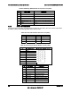
Pin Signal Description Pin
Signal Description
B73 GND GND A73 PERN13 NC
B74 PETP14 NC A74 GND GND
B75 PETN14 NC A75 GND GND
B76 GND GND A76 PERP14 NC
B77 GND GND A77 PERN14 NC
B78 PETP15 NC A78 GND GND
B79 PETN15 NC A79 GND GND
B80 GND GND A80 PERP15 NC
B81 PRSNT2_N NC A81 PERN15 NC
B82 RSVD NC A82 GND GND
6.7 Fan Headers
The server board provides five SSI-compliant 4-pin fan headers to be used as the CPU and
chassis.
CPU fan (J6D1)
SYS1 fan (J1J4)
SYS2 fan (J6J2)
SYS3 fan (J7J1)
SYS4 fan (J6B1)
The pin configuration for each of the 4-pin fan headers is identical and defined in the following
table.
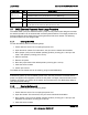
Table 64. SSI 4-pin Fan Header Pin-out (J6E1, J1J4, J6J2, J7J1, J6B1)
Pin Signal Name Type Description
1 Ground GND Ground is the power supply ground
2 12 V Power Power supply 12 V
3 Fan Tach In FAN_TACH signal is connected to the Integrated BMC to monitor the fan
speed
4 Fan PWM Out FAN_PWM signal to control fan speed