
Specifications


Intel® Server Board S3420GPRX TPS Connector/Header Locations and Pin-outs
Revision 1.1
Intel order number E92065-001
89
6.5.7 USB Connector
There are two external USB ports on one NIC/USB combination. The following table contains
the detailed pin-out of the connector.
Two 2x5 connector on the server board (J1E3, J1D2) provides an option to support an
additional USB port, each connector supporting two USB ports. The following table defines the
pin-out of the connector.
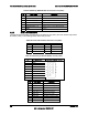
Table 60. Internal USB Connector Pin-out ( J1E3, J1D2)
Pin Signal Name Description
1 USB2_VBUS4 USB power (port 4)
2 USB2_VBUS5 USB power (port 5)
3 USB_ICH_P4N_CONN USB port 4 negative signal
4 USB_ICH_P5N_CONN USB port 5 negative signal
5 USB_ICH_P4P_CONN USB port 4 positive signal
6 USB_ICH_P5P_CONN USB port 5 positive signal
7 Ground
8 Ground
9 Key No pin
10 TP_USB_ICH_NC Test point
The connector (J1J2) on the server board provides an option to support a USB floppy connector.
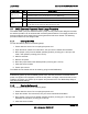
Table 61. Pin-out of Internal USB Connector for Floppy ( J1J2)
Pin Signal Name
1 +5V
2 USB_N
3 USB_P
4 GND
One low-profile 2x5 connectors (J3F2) on the server board provides an option to support an
Intel
®
Z-U130 Value Solid State Drive. The following table defines the pin-out of the connector.
Table 62. Pin-out of Internal USB Connector for low-profile Intel
®
Z-U130 Value Solid State Drive
(J3F2)
Pin Signal Name Description
1 +5V USB power
2 NC N/A
3 USB Data - USB port ## negative signal
4 NC N/A
5 USB Data + USB port ## positive signal
6 NC N/A
7 Ground N/A