Intel® Server Board SE7221BK1-E Technical Product Specification Intel order number C91860-001 Revision 1.
SE7221BK1-E Technical Product Specification Revision History Date Revision Number Modifications July 2004 0.5 Preliminary Release; subject to change. September 2004 0.8 Revised technical details of PCI subsystem, memory support and GMCH. September 2004 0.9 Revised connectors section October 2004 1.0 Released revision November 2004 1.1 Corrected supported CPU matrix January 2005 1.2 Added Diagnostic LED codes to error handling and reporting section February 2005 1.
SE7221BK1-E Technical Product Specification Disclaimers Information in this document is provided in connection with Intel® products. No license, express or implied, by estoppels or otherwise, to any intellectual property rights is granted by this document.
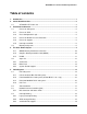
SE7221BK1-E Technical Product Specification Table of contents 1. Introduction .......................................................................................................................... 1 2. Server Board Overview ........................................................................................................ 2 2.1 3. Functional Architecture ....................................................................................................... 5 3.1 Processor VRD ...............
SE7221BK1-E Technical Product Specification 5.5 6. ACPI Implementation ......................................................................................................... 23 6.1 7. 8. ACPI ...................................................................................................................... 23 6.1.1 Front Panel Switches............................................................................................. 23 6.1.2 Wake up Sources (ACPI and Legacy) .......................
SE7221BK1-E Technical Product Specification 9.5.6 Server menu .......................................................................................................... 48 9.5.7 Exit menu............................................................................................................... 51 9.6 Upgrading the BIOS............................................................................................... 51 9.6.1 Preparing for the Upgrade .................................................
SE7221BK1-E Technical Product Specification 13.1.2 Product EMC Compliance ..................................................................................... 76 13.1.3 Product Regulatory Compliance Markings ............................................................ 76 13.2 Electromagnetic Compatibility Notices .................................................................. 77 13.2.1 FCC (USA)......................................................................................................
SE7221BK1-E Technical Product Specification List of Tables Table 1. Processor Support Matrix .............................................................................................. 6 Table 2. Memory Bank Labels and DIMM Population Order........................................................ 8 Table 3. Characteristics of Dual/Single Channel Configuration with/without Dynamic Mode ...... 9 Table 4. Supported DDR2 modules ................................................................................
SE7221BK1-E Technical Product Specification Table 33. Three-pin Fan Headers Pin-out (JP5J1, JP5J2, JP7A1, JP6A1)............................... 31 Table 34. Eight-pin Fan Header Pin-out (J6J1, J6J2, J6J3, and J6J4)...................................... 32 Table 35. Intrusion Cable Connector (J1A1)Pin-Out ................................................................. 32 Table 36. HDD LED Header (J1E1) Pin-Out.............................................................................. 32 Table 37.
SE7221BK1-E Technical Product Specification Table 68. BIOS Recovery Beep Codes ..................................................................................... 57 Table 69. POST Error Messages and Handling......................................................................... 57 Table 70. POST Code Checkpoints............................................................................................ 58 Table 71. Bootblock Initialization Code Checkpoints .............................................
SE7221BK1-E Technical Product Specification List of Figures Figure 1. Intel® Server Board SE7221BK1-E Diagram .............................................................. 4 Figure 2. Memory Bank Label Definition...................................................................................... 8 Figure 3. Interrupt Routing Diagram .......................................................................................... 20 Figure 4. ICH6R Interrupt Routing Diagram......................................
SE7221BK1-E Technical Product Specification 1. Introduction This Intel® Server Board SE7221BK1-E Technical Product Specification (TPS) provides a highlevel technical description for the Intel® Server Board SE7221BK1-E. It details the architecture and feature set for all functional sub-systems that make up the server board. This document is divided into the following main categories: Chapter 2. Server Board Overview Chapter 3. Functional Architecture Chapter 4. The Intel® E7221 Chipset Chapter 5.
SE7221BK1-E Technical Product Specification 2. Server Board Overview 2.
SE7221BK1-E Technical Product Specification USB 2.0 Two external Universal Serial Bus (USB) ports with an additional internal header providing two optional USB ports for front panel support.
SE7221BK1-E Technical Product Specification A B C D E F G H I J EE DD CC BB AA Z K CPU X DIMM 1B Socket DIMM 2B Socket Y DIMM 1A Socket DIMM 2A Socket Socket M L W V U T S R QP O N TP01326 Figure 1.
SE7221BK1-E Technical Product Specification 3. Functional Architecture This chapter provides a high-level description of the functionality distributed between the architectural blocks of the Intel® Server Board SE7221BK1-E. 3.
SE7221BK1-E Technical Product Specification LGA775 processor socket supporting 800MHz FSB Intel® Pentium® 4 processor. Processor host bus AGTL+ support circuitry. Table 1. Processor Support Matrix Processor Family Pentium® 4 Package Type LGA775 Frequency 3.0 - 3.8 GHz Cache Size 2MB L2 Front Side Bus 800MHz Pentium® 4 LGA775 2.8 - 3.8 GHz 1MB L2 800MHz Celeron® D LGA775 2.26 - 2.
SE7221BK1-E Technical Product Specification The maximum memory capacity is 4 GB Note* Although the Intel® Server Board SE7221BK1-E supports a maximum memory capacity of 4 GB, system resources consume roughly 750 MB of physical memory in the maximum memory configuration. As a result, when 4 GB of memory is used, the amount of memory made available to the operating system is significantly lower than 4 GB; roughly 3200 MB. THIS IS ONLY AN ISSUE WHEN 4 GB OF MEMORY IS USED.
SE7221BK1-E Technical Product Specification Table 2. Memory Bank Labels and DIMM Population Order Location DIMM Label Channel Population Order J8J1 (DIMM_1A) A 1 J8J2 (DIMM_2A) A 3 J9J2 (DIMM_1B) B 2 J9J1 (DIMM_2B) B 4 1 J8J1 DIMM_1A 3 2 J8J2 J9J2 J9J1 DIMM_2A DIMM_1B Channel A (Bank 1) 4 DIMM_2B Channel B (Bank 2) Figure 2.
SE7221BK1-E Technical Product Specification Table 3.
SE7221BK1-E Technical Product Specification interfaces that can be independently configured to operate in PCI (33 or 66 MHz), PCI-X Mode1 (66,100,133), for either 32 or 64 bits. 4.1.1 GMCH Memory Architecture Overview The GMCH supports a 72-bit wide memory sub-system that can support a maximum of 4 GB of DDR2 memory using 1 GB DIMMs. This configuration needs external registers for buffering the memory address and control signals.
SE7221BK1-E Technical Product Specification A PCI Express* bus which provides an interface to the PCI-Express* devices( Fully compliant to the PCI Express* Base Specification, Rev 1.0a) A DMI which provides an interface to the ICH6R Other features provided by the GMCH include the following: 4.1.
SE7221BK1-E Technical Product Specification 4.1.3.2 One slots capable of supporting full length legacy PCI add-in cards operating at 33 MHz PCI Express* X4 Subsystem The ICH6R supports one x4-lane PCI Express* interface that can also be configured as a single x1 or x4-lane port. The PCI Express* interface allows direct connection with the PXH/PXHD or PCI-E devices. (Fully compliant to the PCI Express* Base Specification, Rev 1.0a) 4.1.3.
SE7221BK1-E Technical Product Specification 4.2 Super I/O National Semiconductor* PC87427Super IO device contains all of the necessary circuitry to control two serial ports, one parallel port, floppy disk, PS/2-compatible keyboard and mouse and hardware monitor controller. The baseboard implements the following features: 4.2.
SE7221BK1-E Technical Product Specification 4.2.1.6 Wake-up Control The Super IO contains functionality that allows various events to control the power-on and power-off the system. 4.2.2 BIOS Flash The board incorporates an Intel® ® 28F320C3 flash memory component. The 28F320C3 is a high-performance 32-megabit memory component that provides 2096K x 16 of BIOS and nonvolatile storage space. The flash device is connected through the X Bus from Super IO. 4.2.
SE7221BK1-E Technical Product Specification unique PCI device ID value for use in configuration cycles. The following table shows the bit to which each IDSEL signal is attached for P32-A devices and the corresponding device description. Table 6. P32-A Configuration IDs IDSEL Value Device 19 Intel® 82541PI LAN (NIC1) 18 PCI Slot 1 (32b/33MHz) 5.1.1.2 P32-A Arbitration P32-A supports two PCI devices: the ICH6R and one PCI bus masters (NIC).
SE7221BK1-E Technical Product Specification and GNTx* are a special case in that they are internal to the host bridge. The following table defines the arbitration connections. Table 9. P32-B Arbitration Connections Baseboard Signals Device PCIX REQ_N0/GNT_N0 Intel® 82541PI LAN (NIC2) 5.1.3 P64-C 66/100-MHz PCI-X Subsystem One 64-bit PCI-X bus segment is directed through the PXH. This PCI-X segment, P64-C, provides two 3.3V 64-bit PCI-X slots or one 3.
SE7221BK1-E Technical Product Specification 5.1.4 PCI-E x8 In this board, Lanes 0~7 are connected to a x8 PCI-E connector directly. It can support x1, x4, x 8 PCI-E add-in cards. Table 12. PCI-E x 8 Connections Lane Device Lane 0~7 Slot 6 (PCI Express* x 8) 5.2 Video Controller The Intel® E7221 GMCH includes an integrated graphics engine that supports standard SVGA drivers with analog display capabilities.
SE7221BK1-E Technical Product Specification For the NIC 2 connector (SE7221BK1LX sku only), the yellow LED indicates network connection when on, and Transmit/Receive activity when blinking. The orange LED indicates 1000-Mbps operation when lit, the green LED indicates 100-Mbps operation when lit and 10Mbps when off. 5.4 Interrupt Routing The board interrupt architecture accommodates both PC-compatible PIC mode and APIC mode interrupts through use of the integrated I/O APICs in the ICH6. 5.4.
SE7221BK1-E Technical Product Specification Table 14. Interrupt Definitions ISA Interrupt Description INTR Processor interrupt. NMI NMI to processor. IRQ0 System timer IRQ1 Keyboard interrupt. IRQ2 Slave PIC IRQ3 Serial port 1 or 2 interrupt from SUPER IO device, user-configurable. IRQ4 Serial port 1 or 2 interrupt from SUPER IO device, user-configurable. IRQ5 IRQ6 Floppy disk. IRQ7 Parallel Port / Generic IRQ8_L Active low RTC interrupt.
SE7221BK1-E Technical Product Specification ICH6 IOAPIC 0 DMI INTERFACE IRQ0 IRQ1 IRQ2 IRQ3 IRQ4 IRQ5 IRQ6 IRQ7 IRQ8 IRQ9 IRQ10 IRQ11 IRQ12 IRQ13 IRQ14 IRQ15 IRQ16 IRQ17 IRQ18 IRQ19 IRQ20 IRQ21 IRQ22 IRQ23 ICH6 ICH6 8259PIC X8 connector X8 PCI-E interface INTR GMCH CPU Figure 3. Interrupt Routing Diagram 20 Revision 1.
SE7221BK1-E Technical Product Specification Super I/O Timer Keyboard Cascade Serial Port2/ISA ISA Floppy/ISA ISA RTC SCI/ISA ISA ISA SERIRQ Mouse/ISA Coprocessor Error SERIRQ ICH6 Interrupt Routing PCI Interface Serialized IRQ Interface Serial Port1/ISA P IDE/ISA Not Used N/A PIRQA# N/A PIRQB# INTEL 82541PI(NIC1) N/A Slot 1 INTC PIRQC# PIRQD# PIRQE# Slot 1 INTA PIRQF# Slot 1 INTB Slot 1 INTD PIRQG# PIRQH# Figure 4.
SE7221BK1-E Technical Product Specification N/A N/A N/A INTEL 82541PI(NIC2) N/A N/A N/A N/A N/A N/A N/A N/A N/A N/A N/A N/A PA PA PA PA PA PA PA PA PA PA PA PA PA PA PA PA IRQ0 IRQ1 IRQ2 IRQ3 IRQ4 IRQ5 IRQ6 IRQ7 IRQ8 IRQ9 IRQ10 IRQ11 IRQ12 IRQ13 IRQ14 IRQ15 Slot 4 INTA, Slot 6 INTA Slot 4 INTB, Slot 6 INTB Slot 4 INTC, Slot 6 INTC Slot 4 INTD, Slot 6 INTD Slot 5 INTD Slot 5 INTA Slot 5 INTB Slot 5 INTC N/A N/A N/A N/A N/A N/A N/A N/A PB PB PB PB PB PB PB PB PB PB PB PB PB PB PB PB IRQ0 IRQ1 IRQ2 IRQ3
SE7221BK1-E Technical Product Specification 6. ACPI Implementation 6.1 ACPI An ACPI-aware operating system generates an SMI to request that the system be switched into ACPI mode. The BIOS responds to enable ACPI mode. The system automatically returns to legacy mode upon hard reset or power-on reset. The SE7221BK1-E platform supports S0, S1, S4, and S5 states.
SE7221BK1-E Technical Product Specification supply through an inverter, and then transition to an ON state. Power Button On to Off (Legacy): The ICH6 is configured to generate an SMI due to a power button event. The BIOS services this SMI and sets the state of the machine in the ICH6 and Super IO to the OFF state. Power Button On to Off (ACPI): If an ACPI operating system is loaded, the power button switch generates a request (via SCI) to the OS to shutdown the system.
SE7221BK1-E Technical Product Specification 7. Connectors 7.1 Main Power Connector The main power supply connection is obtained using the 24-pin connector. The following table defines the pin-outs of the connector. Table 16. Power Connector Pin-out (CN4H1) Pin Signal 18 AWG Color Pin Signal 18 AWG Color 1* +3.3VDC Orange 13 +3.3VDC Orange 3.3V RS Orange (24AWG) 14 -12VDC Blue 2 +3.
SE7221BK1-E Technical Product Specification 7.2 I2C Header Table 18. HSBP Header Pin-out (J1D1) Pin Signal Name Description 1 HR_SMB_5V_DAT Data Line 2 GND GROUND 3 HR_SMB_5V_CLK Clock Line 4 GND GROUND Table 19. LCD Header Pin-out (J1C1) Pin Signal Name Description 1 HR_SMB_5V_DAT Data Line 2 GND GROUND 3 HR_SMB_5V_CLK Clock Line 4 P5V_STBY POWER Table 20.
SE7221BK1-E Technical Product Specification Signal Name Pin Pin Signal Name FP_PWR_BTN_N 11 12 LAN1_ACT_N GND 13 14 LAN1_LINK_UP_N FP_RST_BTN_N 15 16 MBMC_SMC_PHL5V_DAT RESET switch (GND) 17 18 MBMC_SMC_PHL5V_CLK NC 19 20 NC GND 21 22 LAN2_ACT_N NMI switch# 23 24 LAN2_LINK_UP_N Key 25 26 Key P5V_STB 27 28 P5V_STB FP_ID_LED_N 29 30 FP_STATUS_LED1_N FP_ID_BTN_N 31 32 P5V GND 33 34 NC Note: NC (No Connect) in this project 7.
SE7221BK1-E Technical Product Specification Signal Name Pin Pin Signal Name P1V8_STB_LAN1 6 14 P3V3_STB LAN1_TRDP2 7 15 LAN1_LINK1000_N LAN1_TRDN2 8 16 LINK100_L Table 24.
SE7221BK1-E Technical Product Specification 7.7 SATA Connector ICH6R integrated a SATA controller with four SATA ports output. The pin-out for these four connectors is listed below. Table 26. SATA Connector Pin-out (J1G1, J1G2, J1J2, J2J1) Pin Signal Name 1 GND 2 SATA0_TX_P 3 SATA0_TX_N 4 GND 5 SATA0_RX_N 6 SATA0_RX_P 7 GND 7.8 USB Connector The following table provides the pin-out for the dual external USB connectors. This connector is combined with a RJ45 (connected to COM2 signals).
SE7221BK1-E Technical Product Specification 7.9 Floppy Connector The board provides a standard 34-pin interface to the floppy drive controller. The following tables detail the pin-out of the 34-pin floppy connector. Table 29.
SE7221BK1-E Technical Product Specification Table 31. 9-pin Header Serial B Port Pin-out (J1B1) Signal Name DCDB Pin 1 Pin 2 Signal Name DSRB RXDB 3 4 RTSB TXDB 5 6 CTSB DTRB 7 8 RIB GND 9 10 Key 7.11 Keyboard and Mouse Connector Two PS/2 ports are provided for use by a keyboard and a mouse. The following table details the pin-out of the PS/2 connectors. Table 32.
SE7221BK1-E Technical Product Specification There are also four 8-pin fan headers. (J6J1, J6J2, J6J3, J6J4) These fan headers have the same pin-out and are detailed below. Table 34. Eight-pin Fan Header Pin-out (J6J1, J6J2, J6J3, and J6J4) Pin 1 Signal Name Fan Power Type Power Description Fan Power with FAN_SPEED_CNTL1 (Fan speed control) 2 Fan Tach Out FAN_TACH signal is connected to the Super IO/LM96000 to monitor the FAN speed.
SE7221BK1-E Technical Product Specification 7.12.4 Rolling BIOS selection header There is a 1x3 pin Header that is used to configure the function of rolling BIOS. The figure below shows the jumper pins and their functions. The factory defaults are set to a primary BIOS mode for each function. Table 37. HDD LED Header (J1E1) Pin-Out Function Rolling BIOS selection Pin – Pin Function 1-2 Primary BIOS (Default) 2-3 8.
SE7221BK1-E Technical Product Specification 2-3 Force erase PASSWORD CLEAR 5-6 Protect 6-7 Erase RECOVERY BOOT 9-10 Normal BOOT 10-11 Recovery BOOT 9. SUPER IO. The system BIOS reads these GPIs status and decides whether or not to execute related task. The clear CMOS status is reflected to ICH6. Defaults are in bold. BIOS Setup Utility The BIOS Setup utility is provided to perform system configuration changes and to display current settings and environment information.
SE7221BK1-E Technical Product Specification Key Option Description ESC Exit The ESC key provides a mechanism for backing out of any field. This key will undo the pressing of the Enter key. When the ESC key is pressed while editing any field or selecting features of a menu, the parent menu is re-entered. When the ESC key is pressed in any sub-menu, the parent menu is re-entered.
SE7221BK1-E Technical Product Specification Key Option Description F10 Save Changes and Exit Pressing F10 causes the following message to appear: Save configuration changes and exit setup? [OK] [Cancel] If “OK” is selected and the Enter key is pressed, all changes are saved and setup is exited. If “Cancel” is selected and the Enter key is pressed, or the ESC key is pressed, the user is returned to where they were before F10 was pressed without affecting any existing values. 9.
SE7221BK1-E Technical Product Specification Feature Language 9.5.2 Options English French German Italian Spanish Help Text Use [ENTER], [Up Arrow], [Down Arrow] to select language. Description Select the current default language used by BIOS. Advanced menu Table 41. BIOS Setup, Advanced Menu Options Feature Options Help Text Description Processor Configuration N/A Configure processors. Selects submenu. IDE Configuration N/A Configure the IDE device(s). Selects submenu.
SE7221BK1-E Technical Product Specification Feature Hyper-Threading Technology Options Enabled Disabled Help Text "ENABLE: Enable CPU Hyperthreading for HT enabled processor(s). Description Controls Hyper-Threading state. Primarily used to support older Operating Systems that do not support Hyper Threading. DISABLE: Disable CPU Hyperthreading for HT enabled processor(s)." Controls Hyperthreading state. Primarily used to support older Operating Systems that do not support Hyperthreading. 9.5.2.
SE7221BK1-E Technical Product Specification Feature Secondary IDE Slave N/A Options Help Text Description While entering setup, BIOS auto Selects submenu with additional device details. detects the presence of IDE devices. This displays the status of auto detection of IDE devices. Third IDE Master N/A While entering setup, BIOS auto Selects submenu with additional device details. detects the presence of IDE devices. This displays the status of auto detection of IDE devices.
SE7221BK1-E Technical Product Specification Feature Block (Multi-Sector Transfer) Options Disabled Auto PIO Mode Auto 0 1 2 3 4 Auto SWDMA0-2 MWDMA0-2 UWDMA0-5 DMA Mode S.M.A.R.T. 32Bit Data Transfer 9.5.2.3 Help Text Disabled: The Data transfer from and to the device occurs one sector at a time. Auto: The data transfer from and to the device occurs multiple sectors at a time if the device supports it. Select PIO Mode. Selcet DMA Mode.
SE7221BK1-E Technical Product Specification Serial Port 2 Address 9.5.2.5 Disabled 3F8/IRQ4 2F8/IRQ3 3E8/IRQ4 2E8/IRQ3 Allows BIOS to Select Serial Port2 Base Addresses. Option that is used by other serial port is hidden to prevent conflicting settings. USB configuration sub-menu Table 47. BIOS Setup, USB Configuration Sub-menu Selections Feature USB Devices Enabled Options N/A USB Function Disabled Enables USB HOST controllers.
SE7221BK1-E Technical Product Specification Emulation Type Device #n Emulation Type 9.5.2.6 Auto Floppy Forced FDD Hard Disk CDROM N/A If Auto, USB devices less than 530 MB will be emulated as Floppy and remaining as hard drive. Forced FDD option can be user to force a HDD formatted drive to boot as FDD (Ex. ZIP drive). Auto Floppy Forced FDD Hard Disk CDROM If Auto, USB devices less than 530 MB will be emulated as Floppy and remaining as hard drive.
SE7221BK1-E Technical Product Specification 9.5.2.7 Memory configuration sub-menu This sub-menu provides information about the DIMM’s detected by BIOS. The DIMM number is printed on the baseboard next to each device. Table 50. BIOS Setup, Memory Configuration Sub-menu Selections Feature DIMM_1A Options Installed Not Installed Help Text Description Informational display. DIMM_1B Installed Not Installed Informational display. DIMM_2A Installed Not Installed Informational display.
SE7221BK1-E Technical Product Specification 9.5.3.1 Boot settings configuration sub-menu selections Table 52. BIOS Setup, Boot Settings Configuration Sub-menu Selections Feature Quick Boot Options Disabled Enabled Help Text Allows BIOS to skip certain tests while booting. This will decrease the time needed to boot the system. Quiet Boot Disabled Enabled Disabled: Displays normal POST messages. Enabled: Displays OEM Logo instead of POST messages.
SE7221BK1-E Technical Product Specification 9.5.3.2.2 Removable drive sub-menu selections Table 55. BIOS Setup, Removable Drives Sub-menu Selections Feature 1st Drive Options Varies Help Text Specifies the boot sequence from the available devices. Description Varies based on system configuration. nth Drive Varies Specifies the boot sequence from the available devices. Varies based on system configuration. 9.5.3.2.3 ATAPI CDROM drives sub-menu selections Table 56.
SE7221BK1-E Technical Product Specification Feature DRAM CAS# Latency Options 3, 2.5, 2 Help Text Select CAS latency to be used Description Greyed when DRAM timing programming are done using SPD. Selects the CAS latency value to be programmed when manual configuration of DRAM parameters are used. DRAM RAS# to CAS# Delay 2 DRAM Clocks 3 DRAM Clocks 4 DRAM Clocks Select RAS# to CAS# delay Greyed when DRAM timing programming are done using SPD.
SE7221BK1-E Technical Product Specification PCI-EX Port Configuration N/A N/A Title VC1 for Root Port Disabled Enabled Enable / Disable VC1 feature VC1 feature setting on PCI Express* Root port 9.5.4.3 PXH Bridge Configuration Table 60.
SE7221BK1-E Technical Product Specification Feature Clear User Password N/A Help Text Immediately clears the user password. Fixed disk boot sector protection Disabled Enabled Enable/Disable Boot Sector Virus Protection. Password On Boot Disabled Enabled If enabled, requires password entry before boot. This node is grayed out if a password is not installed.
SE7221BK1-E Technical Product Specification Feature Assert NMI on PERR Options Disabled Enabled Assert NMI on SERR Disabled Enabled Help Text If enabled, NMI is generated. SERR option needs to be enabled to activate this option. If enabled, NMI is generated on SERR and logged. Resume on AC Power Loss Stays Off Power On Determines the mode of operation if a power loss occurs. Stays off, the system will remain off once power is restored. Power On, boots the system after power is restored.
SE7221BK1-E Technical Product Specification PIA Revision N/A N/A Field contents varies SDR Revision N/A N/A Field contents varies 9.5.6.2 Serial Console features sub-menu selections Table 64. BIOS Setup Serial Console Features Sub-menu Selections Feature BIOS Redirection Port Options Disabled Serial 1 Serial 2 Help Text If enabled, BIOS uses the specified serial port to redirect the console to a remote ANSI terminal. Enabling this option disables Quiet Boot.
SE7221BK1-E Technical Product Specification Feature ECC Event Logging Options Disabled Enabled Help Text Enables or Disables ECC Event Logging. Description Grayed out if "Critical Event Logging" option is disabled. PCI Error Logging Disabled Enabled Enables or Disables PCI Error Logging. Grayed out if "Critical Event Logging" option is disabled. 9.5.7 Exit menu Table 66.
SE7221BK1-E Technical Product Specification If you chose to “Save Custom Defaults,” after the new BIOS is flashed, you can restore your settings from the “Load Custom Default” option. 9.6.1.2 Obtaining the Upgrade Utility You can upgrade to a new version of the BIOS using the new BIOS files and the BIOS upgrade utility. You can obtain the BIOS upgrade file and the utility from the Intel Customer Support Web site: http://support.intel.com/support/motherboards/server/SE7221BK1-E. 9.6.1.
SE7221BK1-E Technical Product Specification Run command afuefi [/n] [/p[b][n][c]] to perform the update.
SE7221BK1-E Technical Product Specification 9.6.3.1 Recovery Mode Three conditions can cause the system to enter recovery mode. Pressing a hot-key, setting the recovery jumper, and damage to both partitions of the ROM image will cause the system to enter recovery and update System ROM without the boot-block. • BIOS Recovery The recovery disk must include the BIOS image file AMIBOOT.ROM. The 2 MB AMIBOOT.ROM file may be used on a 2.88MB floppy media (to go with a 2.
SE7221BK1-E Technical Product Specification 4) After reading the file it increments the file extension and then searches for AMIBOOT.001 in the same floppy. 5) If doesn't find the file in the floppy it will beep for once (1sec) and search again. 6) If it finds the first file and if it needs more files it will increment the file extension and searches again for AMIBOOT.002 this time it beeps 2 times (each beep 1sec long and with 0.
SE7221BK1-E Technical Product Specification 9) Plug the system into the AC power source and power it up to confirm that the recovery was successful. Figure 7. BIOS Recovery Jumper 9.7 9.7.1 Error Handling and Reporting POST Error Beep Codes Table 67. POST Error Beep Codes Beeps 1 Error Message Fatal error 2 Processor error 3 Memory error 4 Motherboard error 56 POST Progress Code Description System halted because of an unspecified fatal error that was detected.
SE7221BK1-E Technical Product Specification Table 68. BIOS Recovery Beep Codes Beeps 1 2 Error Message Recovery Started Recovery Boot Error Series of long low-pitched single beeps 2 long highpitched beeps Recovery Failed POST Progress Code E9h Flashing series of POST codes: EFh, FAh, FBh, F4h, FCh, FDh, FFh FDh Recovery Complete FFh 9.7.2 Description Start of recovery process Unable to boot to floppy, ATAPI, or ATAPI CD-ROM. Recovery process will retry. Unable to process valid BIOS recovery images.
SE7221BK1-E Technical Product Specification Error Code Error Message Response LANGUAGE_MODULE_ERR) 14D Primary Master Hard Disk Error Pause 14E Primary Slave Hard Disk Error Pause 14F Secondary Master Hard Disk Error Pause 150 Secondary Slave Hard Disk Error Pause 151 Primary Master Drive - ATAPI Incompatible Pause 152 Primary Slave Drive - ATAPI Incompatible Pause 153 Secondary Master Drive - ATAPI Incompatible Pause 154 Secondary Slave Drive - ATAPI Incompatible Pause 8100 Pro
SE7221BK1-E Technical Product Specification Checkpoint 05 Description Initializes the interrupt controlling hardware (generally PIC) and interrupt vector table. 06 Do R/W test to CH-2 count reg. Initialize CH-0 as system timer. Install the POSTINT1Ch handler. Enable IRQ-0 in PIC for system timer interrupt. Traps INT1Ch vector to "POSTINT1ChHandlerBlock." 08 Initializes the CPU. The BAT test is being done on KBC.
SE7221BK1-E Technical Product Specification Checkpoint 7A Initializes remaining option ROMs. 7C Generate and write contents of ESCD in NVRam. 84 Log errors encountered during POST. 85 Display errors to the user and gets the user response for error. 87 Execute BIOS setup if needed / requested. 8C Late POST initialization of chipset registers. 8D Build ACPI tables (if ACPI is supported) 8E Program the peripheral parameters.
SE7221BK1-E Technical Product Specification 9.7.3.2 Boot Block Initialization Code Checkpoints The Boot Block initialization code sets up the chipset, memory and other components before system memory is available. The following table describes the type of checkpoints that may occur during the boot block initialization. Table 71. Bootblock Initialization Code Checkpoints Checkpoint Before D1 Description Early chipset initialization is done.
SE7221BK1-E Technical Product Specification 9.7.3.3 Boot Block Recovery Code Checkpoints The Boot block recovery code gets control when the BIOS determines that a BIOS recovery needs to occur because the user has forced the update or the BIOS checksum is corrupt. The following table describes the type of checkpoints that may occur during the Bootblock recovery portion of the BIOS: Table 72.
SE7221BK1-E Technical Product Specification 9.7.3.4 DIM Code Checkpoints The Device Initialization Manager Module gets control at various times during BIOS POST to initialize different BUSes. The following table describes the main checkpoints where the DIM module is accessed. Table 73.
SE7221BK1-E Technical Product Specification 9.8 Diagnostic LEDs All port 80 codes are displayed using the Diagnostic LEDs found on the back edge of the baseboard. The diagnostic LED feature consists of a hardware decoder and four dual color LEDs. During POST, the LEDs will display all normal POST codes representing the progress of the BIOS POST. Each code will be represented by a combination of colors from the four LEDs. The LEDs are capable of displaying three colors: Green, Red, and Amber.
SE7221BK1-E Technical Product Specification Diagnostic LED Decoder G=Green, R=Red, A=Amber Hi Low Description 15h Off G Off A Pass control to the uncompressed code in shadow RAM. The initialization code is copied to segment 0 and control will be transferred to segment 0. 16h Off G G R Control is in segment 0. Verify the system BIOS checksum. If the system BIOS checksum is bad, go to checkpoint code E0h. Otherwise, going to checkpoint code D7h.
SE7221BK1-E Technical Product Specification Diagnostic LED Decoder G=Green, R=Red, A=Amber Hi Description Low 34h Off G R R Keyboard Init: The keyboard controller command byte is written. Next, issuing the pin 23 and 24 blocking and unblocking commands 36h Off G A R Disable and initialize 8259 38h G Off R R Detect Configuration Mode, such as CMOS clear. 3Ah G Off A R Chipset Initialization before CMOS initialization 3Ch G G R R Init System Timer: The 8254 timer test is over.
SE7221BK1-E Technical Product Specification Diagnostic LED Decoder G=Green, R=Red, A=Amber Hi Description Low 78h G R R R Extended background memory test start 7Ah G R A R Disable parity and NMI reporting. 7Ch G A R R Test 8237 DMA Controller: The DMA page register test passed. Performing the DMA Controller 1 base register test next 7Eh G A A R Init 8237 DMA Controller: The DMA controller 2 base register test passed. Programming DMA controllers 1 and 2 next.
SE7221BK1-E Technical Product Specification 10. Power Information 10.1 Intel® Server Board SE7221BK1-E Power Budget The following table shows the power consumed on each supply line for the SE7221BK1-E baseboard that is configured with one processor (128W max). This configuration includes four 1 GB DDR2 DIMMs stacked burst at 70% max. The numbers provided in the table should be used for reference purposes only. Different hardware configurations will produce different numbers.
SE7221BK1-E Technical Product Specification 10.2 Power Supply Specifications This section provides power supply design guidelines for the baseboard, including voltage and current specifications, and power supply on/off sequencing characteristics. Table 79. The Board Power Supply Voltage Specification PARAMETER TOLERANCE MIN NOM MAX UNITS + 3.3V - 5% / +5% +3.14 +3.30 +3.46 Vrms + 5V - 5% / +5% +4.75 +5.00 +5.25 Vrms + 12V - 5% / +5% +11.40 +12.00 +12.
SE7221BK1-E Technical Product Specification Vout V1 10% Vout V2 V3 V4 Tvout_off Tvout_rise Tvout_on Figure 8. Output Voltage Timing Table 81. Turn On/Off Timing Item Description Tsb_on_delay MIN MAX UNITS Delay from AC being applied to 5VSB being within regulation. 1500 msec T ac_on_delay Delay from AC being applied to all output voltages being within regulation. 2500 msec Tvout_holdup Time all output voltages stay within regulation after loss of AC.
SE7221BK1-E Technical Product Specification AC Input Tvout_holdup Vout Tpwok_low TAC_on_delay Tsb_on_delay PWOK 5VSB Tpwok_off Tpwok_on Tsb_on_delay Tpwok_on Tpwo Tpson_pw Tpwok_holdup T5VSB_holdup Tsb_vout Tpson_on_delay PSON AC turn on/off cycle PSON turn on/off cycle Figure 9. Turn On/Off Timing (Power Supply Signals) 10.2.2 Dynamic Loading The output voltages shall remain within limits specified for the step loading and capacitive loading specified in the table below.
SE7221BK1-E Technical Product Specification 10.2.3 AC Line Transient Specification AC line transient conditions shall be defined as “sag” and “surge” conditions. “Sag” conditions are also commonly referred to as “brownout”, these conditions will be defined as the AC line voltage dropping below nominal voltage conditions. “Surge” will be defined to refer to conditions when the AC line voltage rises above nominal voltage.
SE7221BK1-E Technical Product Specification Table 85. Absolute Maximum Ratings Operating Temperature 5 °C to 50 °C 1 Storage Temperature -55 °C to +150 °C Voltage on any signal with respect to ground -0.3 V to Vdd + 0.3V 2 3.3 V Supply Voltage with Respect to ground -0.3 V to 3.63 V 5 V Supply Voltage with Respect to ground -0.3 V to 5.5 V Notes: 1. 2. Chassis design must provide proper airflow to avoid exceeding the processor maximum case temperature.
SE7221BK1-E Technical Product Specification Temperature 74 FANIN0 (PIN #66) Monitors SYS FAN_2 (JP7A1) / SYS FAN_5A (J6J1) Super IO FANIN1 (PIN #81) Monitors SYS FAN_1 (JP6A1) / SYS FAN_5B (J6J1) Super IO FANIN2 (PIN #77) Monitors SYS FAN_6A (J6J2) Super IO FANIN3 (PIN #76) Monitors SYS FAN_6B (J6J2) Super IO FANIN4 (PIN #75) Monitors SYS FAN_8A (J6J4) Super IO FANIN5 (PIN #83) Monitors SYS FAN_8B (J6J4) Super IO FANIN6 (PIN #36) Monitors SYS FAN_7A (J6J3) Super IO FANIN7 (PIN #9) Monitors
SE7221BK1-E Technical Product Specification 12.2 Fan Speed Control LM96000 PWM1 PWM CKT CPU FAN J7A11 SYS FAN3 JP5J1 FAN SPEED CNTL1 PWM2 TACH1 SYS FAN4 TACH2 TACH3 SYS FAN2 SYS FAN1 Super IO PC87427 JP5J2 JP7A1 JP6A1 FANIN0 SYS FAN5 A B FANIN1 FANIN2 FANIN3 SYS FAN6 A J6J1 J6J2 B FANIN4 SYS FAN8 A FANIN5 J6J4 B FANIN6 .................... SYS FAN7 J6J3 A FANIN7 B Figure 10.
SE7221BK1-E Technical Product Specification 12.3 Chassis Intrusion The Intel® Server Board SE7221BK1-E supports a chassis security feature that detects if the chassis cover is removed. For the chassis intrusion circuit to function, the chassis’ power supply must be connected to AC power. The security feature uses a mechanical switch on the chassis that attaches to the chassis intrusion connector. When the chassis cover is removed the mechanical switch is in the closed position. 13.
SE7221BK1-E Technical Product Specification Table 87. Product Certification Markings UL Recognition Mark CE Mark Russian GOST Mark Australian C-Tick Mark BSMI DOC Marking BSMI EMC Warning RRL MIC Mark 13.2 Electromagnetic Compatibility Notices 13.2.1 FCC (USA) This device complies with Part 15 of the FCC Rules.
SE7221BK1-E Technical Product Specification cause harmful interference to radio or television reception, which can be determined by turning the equipment off and on, the user is encouraged to try to correct the interference by one or more of the following measures: Reorient or relocate the receiving antenna. Increase the separation between the equipment and the receiver. Connect the equipment to an outlet on a circuit other than the one to which the receiver is connected.
SE7221BK1-E Technical Product Specification The English translation for the above is as follows: 1. Type of Equipment (Model Name): SE7221BK1-E 2. Certification No.: Contact Intel Representative 3. Name of Certification Recipient: Intel 4. Date of Manufacturer: Marked on Product 5. Manufacturer / Nation : Intel 13.2.6 Australia / New Zealand This product has been tested and complies with AS/NZS 3548. The product has been marked with the C-Tick mark to illustrate compliance. 13.
SE7221BK1-E Technical Product Specification 13.4 Calculated Mean Time Between Failures (MTBF) The MTBF (Mean Time Between Failures) for the Intel® Server Board SE7221BK1-E as configured from the factory is shown in the table below. Table 88. MTBF Data SE7221BK1 Product Code Calculated MTBF TBD hours Operating Temperature 35 degrees C SE7221BK1LX TBD hours 35 degrees C 13.5 Mechanical Specifications The following figure shows the Intel® Server Board SE7221BK1-E mechanical drawing.
SE7221BK1-E Technical Product Specification Figure 11.
SE7221BK1-E Technical Product Specification The following figures show the I/O shield mechanical drawings for use in pedestal mount applications such as the Intel® Server Chassis SC5200 for both sku ’s (SE7221BK1-E and SE7221BK1-E (LX). Figure 12. sku 1 Pedestal mount I/O shield mechanical drawing 82 Revision 1.
SE7221BK1-E Technical Product Specification Figure 13.
Glossary SE7221BK1-E Technical Product Specification Glossary This appendix contains important terms used in the preceding chapters. For ease of use, numeric entries are listed first (e.g., “82460GX”) with alpha entries following (e.g., “AGP 4x”). Acronyms are then entered in their respective place, with non-acronyms following.
Glossary SE7221BK1-E Technical Product Specification Term Definition LPC Low pin count LSB Least Significant Bit MB 1024 KB MBE Multi-Bit Error Ms milliseconds MSB Most Significant Bit MTBF Mean Time Between Failures Mux multiplexor NIC Network Interface Card NMI Non-maskable Interrupt OEM Original equipment manufacturer Ohm Unit of electrical resistance PBGA Pin Ball Grid Array PERR Parity Error PIO Programmable I/O PMB Private Management Bus PMC Platform Management Con
SE7221BK1-E Technical Product Specification Term Glossary Definition USB Universal Serial Bus VGA Video Graphic Adapter VID Voltage Identification VRM Voltage Regulator Module Word 16-bit quantity ZCR Zero Channel RAID III