
Technical Product Specification


Power Sub-system Intel® Server Chassis SC5650 TPS
Revision 1.2
Intel order number E39531-004
14
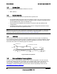
Table 3. Cable Lengths
From To Connector #
Length
(mm)
Number of
Pins
Description
Power Supply cover exit
hole
P1 850 24 Baseboard Power Connector
From To Connector #
Length
(mm)
Number of
Pins
Description
Power Supply cover exit
hole
P2 400 8 Processor 0 Power Connector
Power Supply cover exit
hole
P3 400 8 Processor 1 Power Connector
Power Supply cover exit
hole
P4 350 5 Power PSMI Connector
Power Supply cover exit
hole
P5 350 4 Peripheral Power Connector
Extension P6 100 4 Peripheral Power Connector
Power Supply cover exit
hole
P7 800 4 Peripheral Power Connector
Extension P8 75 4 Peripheral Power Connector
Power Supply cover exit
hole
P9
800
5
Right-angle SATA Power
Connector
Extension P10 75 5 SATA Power Connector
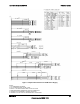
2.1.3.1 P1 Baseboard Power Connector
Connector housing: 24-pin Molex* Mini-Fit Jr.
39-01-2245 or equivalent
Contact: Molex* 39-00-0059, or equivalent; Molex* 44476-1111 for P10 & P11
Table 4. P1 Baseboard Power Connector
Pin Signal 18 AWG Color Pin Signal 18 AWG Color
1 +3.3 VDC Orange 13 +3.3 VDC Orange
2 +3.3 VDC Orange 14 -12 VDC Blue
3 COM Black 15 COM Black
4 +5 VDC Red 16 PSON# Green
5 COM Black 17 COM Black
6 +5 VDC Red 18 COM Black
7 COM Black 19 COM Black
8 PWR OK Gray 20 Reserved N.C.
9 5VSB Purple 21 +5 VDC Red
10 +12V3 Yellow 22 +5 VDC Red
11 +12V2 Yellow 23 +5 VDC Red
12 +3.3 VDC Orange 24 COM Black