
Technical Product Specification


Intel® Server Chassis SC5650 TPS Power Sub-system
Revision 1.2
Intel order number E39531-004
79
sensing errors. The power supply operates within specification over the full range of voltage
drops from the power supply’s output connector to the remote sense points.
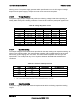
2.4.8.6 Voltage Regulation
The power supply output voltages stay within the following voltage limits when operating at
steady state and dynamic loading conditions. These limits include the peak-peak ripple/noise.
Table 89. Voltage Regulation Limits
Parameter Tolerance MIN NOM MAX Units
+ 3.3V - 5% / +5% +3.14 +3.30 +3.46 V
rms
+ 5V - 5% / +5% +4.75 +5.00 +5.25 V
rms
+ 12V1 - 5% / +5% +11.40 +12.00 +12.60 V
rms
+ 12V2 - 5% / +5% +11.40 +12.00 +12.60 V
rms
+12V3 - 5% / +5% +11.40 +12.00 +12.60 V
rms
+12V4 - 5% / +5% +11.40 +12.00 +12.60 V
rms
+12V5 - 5% / +5% +11.40 +12.00 +12.60 V
rms
- 12V - 5% / +9% -10.80 -12.00 -13.20 V
rms
+ 5VSB - 5% / +5% +4.75 +5.00 +5.25 V
rms
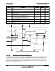
2.4.8.7 Dynamic Loading
The output voltages remain within limits specified for the step loading and capacitive loading, as
shown in the following table. The load transient repetition rate is tested between 50 Hz and 5
kHz at duty cycles ranging from 10%-90%. The load transient repetition rate is only a test
specification. The Δ step load may occur anywhere between the MIN load and MAX load
conditions.
Table 90. Transient Load Requirements
Output Δ Step Load Size
12
Load Slew Rate Test Capacitive Load
+3.3V 7.0A
0.25 A/μsec 4700 μF
+5V 7.0A
0.25 A/μsec 1000 μF
+12V 25A
0.25 A/μsec 4700 μF
+5VSB 0.5A
0.25 A/μsec 20 μF
1. Step loads on each 12V output may happen simultaneously.
2. The +12V should be tested with 2200μF evenly split between the four +12V rails.
2.4.8.8 Capactive Loading
The power supply is stable and meets all requirements with the following capacitive loading
ranges.