
Technical Product Specification


Power Sub-system Intel® Server Chassis SC5650 TPS
Revision 1.2
Intel order number E39531-004
38
2.2.3 DC Output Specification
2.2.3.1 Connector
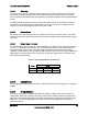
The power supply provides card edge fingers, which mate to a connector located inside the
system. It is a blind-mating type of connector that connects the power supply’s output voltages
and signals. The card edge finger pin assignments are defined in the following table.
Table 33. Edge Finger Power Supply Connector Pin-out
Connector Upper Side Pin No
Top.
Pin No.
Bottom
Bottom Side
+12 V 1 2 +12 V
+12 V 3 4 +12 V
+12 V 5 6 +12 V
+12 V 7 8 +12 V
+12 V 9 10 +12 V
+12 V 11 12 +12 V
+12 V 13 14 +12 V
+12 V 15 16 +12 V
+12 V 17 18 +12 V
+12 V Return 19 20 +12 V Return
+12 V Return 21 22 +12 V Return
+12 V Return 23 24 +12 V Return
+12 V Return 25 26 +12 V Return
+12 V Return 27 28 +12 V Return
+12 V Return 29 30 +12 V Return
+12 V Return 31 32 +12 V Return
+12 V Return 33 34 +12 V Return
+12 V Return 35 36 +12 V Return
+12 V Return 37 38 +12 V Return
5 VSB 39 40 ALERT
5 VSB 41 42 +12 V Sharing
+15 VCC 43 44 POK
PS_KILL 45 46 -PS_Present
PS_ON_CTL 47 48 A0
Gold finger edge
connector: 2X25
SCL 49 50 -OVER_TEMP
Signals that are defined as low true or high true use the following convention:
Signal# = low true
Reserved pins are reserved for future use.