
Service Guide


Hardware Installations and Upgrades
Intel®
Server
Chassis SC5600 Service Guide 53
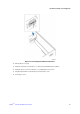
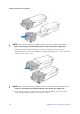
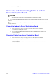
Figure 62. Inserting Hot Swap Power Supply Cage in Chassis
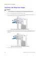
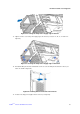
13. Tighten screws to secure the power supply cage to the chassis (see letters “A”, “B”, “C”, “D” and “E” in
Figure 63).
Figure 63. Securing Hot Swap Power Supply Cage to Chassis
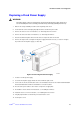
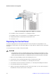
14. Reinstall the filler panel board, and install the screws to secure the filler panel board to the chassis (see
letters “A” and “B” in Figure 64).
Figure 64. Installing Filler Panel board on the Chassis
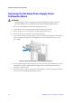
15. Insert the hot swap power supplies into the chassis (see Figure 65).