
Technical Product Specification


Intel® Server Chassis SC5600 Chassis Power Subsystem
Revision 1.1
Intel order number E39532-004
49
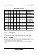
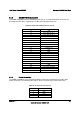
5.3.4.2 Over Voltage Protection (OVP)
Each DC/DC converter output on the power distribution board has individual OVP protection
circuits built in and locally sensed. The power supply shall shut down and latch off after an over
voltage condition occurs. This latch can be cleared by toggling the PSON
#
signal or by an AC
power interruption. The values are measured at the power distribution board harness
connectors. The voltage shall never exceed the maximum levels when measured at the power
pins of the output harness connector during any single point of fail. The voltage shall never trip
any lower than the minimum levels when measured at the power pins of the power distribution
board connector.
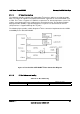
5.3.5 Control and Indicator Functions
The following sections define the input and output signals from the power distribution board.
Signals that can be defined as low true use the following convention:
signal
#
= low true
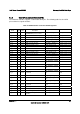
5.3.5.1 PSON
#
Input and Output Signals
The PSON
#
signal is required to remotely turn on/off the power supply. There is the PSON#
Input receiving the signal from the system and there is the PSON# Output signal leading from
the PDB to both power supplies (in 1+1 configuration).
5.3.5.2 PSKILL
The purpose of the PSKill pin is to allow for hot-swapping of the power supply. The mating pin of
this signal on the power distribution board input connector should be tied to ground, and its
resistance shall be less than 5 ohms.
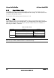
5.3.5.3 PWOK (Power OK) Input and Output Signals
PWOK is a Power ok signal, which will be pulled HIGH by the power supply to indicate its +12 V
output is within its regulation limits. When its +12 V output voltage falls below regulation limits or
when AC power is removed for a time sufficiently long enough so that the power supply
operation is no longer guaranteed, PWOK is de-asserted to a LOW state.
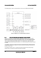
5.3.5.4 SMBALERT
#
Output Signal
This signal indicates the power supply is experiencing a problem the user should investigate.
The SMBALERT# output signal going to the system (an interrupt) is the AND function of the
following nine logic signals:
1. PSAlert#_1
2. PSAlert#_2
3. 12V1_OCP
4. 12V2_OCP
5. 12V3_OCP
6. 12V4_OCP