
Technical Product Specification


Intel® Server Chassis SC5600 Chassis Power Subsystem
Revision 1.1
Intel order number E39532-004
39
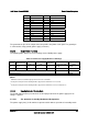
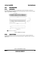
Pin Solder Side Pin Component Side
24 +12 V 47 +12 V
25 +12 V 46 +12 V
26 +12 V 45 +12 V
27 +12 V 44 +12 V
28 +12 V 43 +12 V
29 +12 V 42 +12 V
30 +12 V 41 +12 V
31 +12 V 40 +12 V
32 +12 V 39 +12 V
33 +12 V 38 +12 V
34 +12 V 37 +12 V
35 +12 V 36 +12 V
The ground of the pins of the output connector provides the power return path. The ground pin
is connected to safety ground (power supply enclosure).
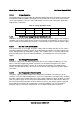
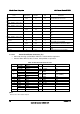
5.2.5.2 Output Power / Currents
The following table defines the current ratings for the 750-W power supply.
Table 25. 750-W Power Supply Module Load Ratings
Voltage Maximum Load
Minimum
Dynamic Load
Minimum Static
Load
Peak Load
Maximum
Continuous Power
Maximum Peak
Power
+12 V 62.0 A 3.0 A 0.0 A 70 A
2
744 W 840 W
+5 VSB 3.0 A 0.1 A 0.1 A 5.0 A
3
15 W 25 W
Total continuous power
1
= 750 W
Total Peak power
2
= 865 W
Notes:
1.
Maximum continuous total DC output power shall not exceed 750 W.
2.
Peak power and peak current loading shall be supported for a minimum of 12 seconds.
3.
Peak power and peak current loading shall be supported for a minimum of 0.5 second at turn-on.
5.2.5.3 Standby Outputs / Standby Mode
The 5 VSB output shall be present when an AC input greater than the power supply turn on
voltage is applied.
5.2.5.3.1 Fan Operation in Standby ModeStand By Operation
The power supply fan(s) shall continue to operate at their lowest speed when in standby mode.