
Technical Product Specification

Chassis Power Subsystem Intel® Server Chassis SC5600
Revision 1.1
Intel order number E39532-004
44
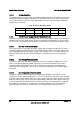
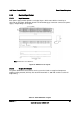
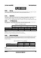
From Length (mm)
To Connector
Number
Number
of
pins
Description
Power Supply cover exit
hole
800 P1 24 Baseboard Power Connector
Power Supply cover exit
hole
350 P2 8 CPU 2 Power Connector
Power Supply cover exit
hole
650 P3 8 CPU 1 Power Connector
Power Supply cover exit
hole
350 P4 5 Power Signal Connector
Power Supply cover exit
hole
250 P5 4
Peripheral Power Connector for 5.25
inch
Extension 100 P6 4
Peripheral Power Connector for 5.25
inch
Extension 100 P7 4
Peripheral Power Connector for 5.25
inch
Power Supply cover exit
hole
600 P8 4 Peripheral Power Connector for HDD
Extension 75 P9 4
Right-angle Peripheral Power Connector
(Cover with sleeve) for HDD
Power Supply cover exit
hole
600 P10 4 Peripheral Power Connector for HDD
Extension 75 P11 4 Peripheral Power Connector for HDD
Power Supply cover exit
hole
600 P12 5
Right-angle SATA Power Connector for
HDD
Extension 75 P13 5 SATA Power Connector for HDD
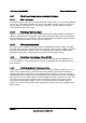
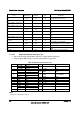
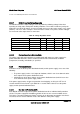
5.3.3.2.1 Server Board Power Connector (P1)
Connector housing: 24-Pin Molex* Mini-Fit Jr. 39-01-2245 or equivalent
Contact: Molex Mini-Fit, HCS, Female, Crimp 44476 or equivalent
Table 29. Baseboard Power Connector
Pin Signal 18 AWG Color
Pin
Signal
18 AWG Color
1
1
+3.3 VDC Orange
13 +3.3 VDC Orange
3.3 V RS Orange (24AWG)
2 +3.3 VDC Orange 14 -12 VDC Blue
3
1
COM Black
15 COM Black
COM RS Black (24AWG)
4
1
+5 VDC Red
16 PSON
#
Green (24AWG)
5 V RS Red (24AWG)
5 COM Black 17 COM Black
6 +5 VDC Red 18 COM Black
7 COM Black 19 COM Black
8 PWR OK Gray (24AWG) 20 Reserved N.C.
9 5 VSB Purple 21 +5 VDC Red
10 +12V3 Yellow 22 +5 VDC Red
11
+12V3 Yellow
23 +5 VDC Red
+12V3 RS Yellow (24AWG)
12 +3.3 VDC Orange 24 COM Black
Note:
1
Remote Sense wire double-crimped.