
Technical Product Specification

Intel® Server Chassis SC5600 Front Panel
Revision 1.1
Intel order number E39532-004
15
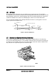
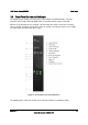
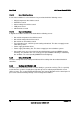
3.3 Front Panel Controls and Indicators
The following figure displays the front panel control buttons and LED indicators. The tool-
activated non-maskable Interrupt (NMI) switch is located below the Status Fault LED.
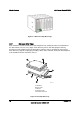
When the hot-swap drive bay is installed, a bi-color hard drive LED is located on each drive
carrier (six total) to indicate specific drive failure or activity. For pedestal systems, these LEDs
are visible when the front bezel door is open.
Figure 13. Front Panel Controls and Indicators
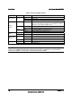
The following table shows the function of the front panel buttons and indicator LEDs.