
Technical Product Specification

Front Panel Intel® Server Chassis SC5600
Revision 1.1
Intel order number E39532-004
14
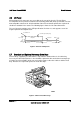
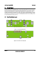
3.2 Front Panel Connectors
The following table lists the front panel connectors.
Table 5. Front Panel Connector Designations
Designator Header Size Description
J4L2 12x2 Front panel SSI connector
J4L1 2x1 Intrusion or front panel key switch
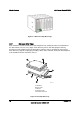
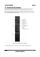
3.2.1
24-pin EEB SSI Compliance Connector Pin-out
A 24-pin Entry-level Electronics Bay (EEB) SSI (rev 3.61) front panel header is located on the
back of the front panel. This allows for a 24-pin ribbon cable connection for use with SSI rev
3.61-compliant server boards.
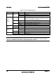
Table 6. 24-pin EEB SSI Compliance Connector Pin-out
Pin Signal Name Description Pin Signal Name Description
1 P3V3_STBY
(Power_LED_Anode)
Power LED + 2 P3V3_STBY Front Panel
Power
3 Key No Connection 4 P5V_STBY (ID
LED Anode)
ID LED +
5 FP_PWR_LED_N Power LED - 6 FP_ID_LED_BUF_
N
ID LED -
7 P3V3
(HDD_ACTIVITY_Ano
de)
HDD Activity
LED +
8 FP_LED_STATUS
_GREEN_N
Status LED
Green -
9 LED_HDD_ACTIVITY_
N
HDD Activity
LED -
10 FP_LED_STATUS
_AMBER_N
Status LED
Amber -
11 FP_PWR_BTN_N Power Button 12 NIC1_ACT_LED_N NIC 1
Activity LED
-
13 GND (Power Button
GND)
Power Button
Ground
14 NIC1_LINK_LED_
N
NIC 1 Link
LED -
15 BMC_RST_BTN_N Reset Button 16 SMB_SENSOR_3V
3STB_DATA
SMB Sensor
DATA
17 BND (Reset GND) Reset Button
Ground
18 SMB_SENSOR_3V
3STB_CLK
SMB Sensor
Clock
19 FP_ID_BTN_N ID Button 20 FP_CHASSIS_INT
RU
Chassis
Intrusion
21 FM_SIO_TEMP_SENS
OR
Front Panel
Temperature
Sensor
22 NIC2_ACT_LED_N NIC 2
Activity LED
-
23 FP_NMI_BTN_N NMI Button 24 NIC2_LINK_LED_
N
NIC 2 Link
LED -