
Technical Product Specification

Chassis Features Intel® Server Chassis SC5600
Revision 1.1
Intel order number E39532-004
8
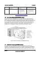
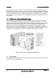
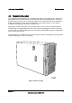
2.4 Rack Mount Configuration
In the rack mount configuration, the front door is removed and the sub-bezel becomes the front
panel for the rack mount system. The drive bays and bezel icons are rotated 90° to have the
correct orientation. The rack mount kit includes the chassis slides, rack handles, front door
hinge cover plate, and icon label.
Figure 4. Rack Configuration
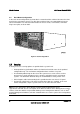
2.5 Security
A variety of chassis security options are provided at the system level:
A two-position key lock/switch unlocks the front bezel and side cover in the pedestal
configuration only. The rack mount configuration does not have a key lock.
A removable padlock loop on the rear of the system access cover can be used to
prevent access to the microprocessors, memory, and add-in cards in rack mount
systems. The 0.270-inch diameter loop can accommodate a variety of lock sizes.
A Kensington* cable lock mounting hole is provided on the rear chassis I/O panel.
An intrusion switch for the side panel and front bezel door are standard. In the rack
mount configuration, only the system cover has an active intrusion switch.
Note: See the appropriate Server Board Technical Product Specification on the
support.intel.com web site for a description of the BIOS and Intel
®
Server Management security
features. Intrusion switches are provided allowing server management software, such as Intel
®
System Management Software, to detect unauthorized access to the system cover and pedestal
bezel door.