
Technical Product Specification

Hot Swap Hard Disk Drive Bays Intel® Server Chassis SC5400 5U Kit TPS
56 Revision: 1.0
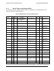
VSC410* Pin
Name
I/O
Type
Power
Well
Programming
Description
System Function Reset
State
Initial
Value
Connection
_N
P2_6 O 3.3V Test Point TP_LED_DRV10_FLT_
N
P2_7 O 3.3V Test Point TP_FM_DRV10_PRSN
T_N
P3_0 I/O 3.3V Clock signal of SGPIO
interface
SGPIO_CLK
P3_1 I/O 3.3V. Load signal of SGPIO
interface
SGPIO_LOAD
P3_2 I/O 3.3V SDATAIN signal of SGPIO
interface
SGPIO_DATAOUT0
P3_3 I/O 3.3V SDATAOUT signal of
SGPIO interface
SGPIO_DATAOUT1
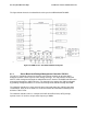
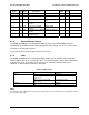
6.1.3 External Memory Device
The 4HDD and 6HDD passive SAS/SATA HSBP contains a non-volatile 8Mbit Serial SPI
FLASH Memory for Boot and Run-Time/Configuration code storage. The device resides on the
SPI interface of VSC410* controller.
The Serial SPI Flash memory operates from the 3.3V rail.
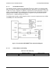
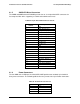
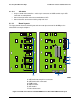
6.1.4 LEDs
The 4HDD and 6HDD passive SAS/SATA HSBP contain a green STATUS LED and amber
FAULT LED for each of the six hard disk drives. The STATUS LED is driven by the SAS/SATA
hard disk drive itself. The FAULT LED is driven by the VSC410* controller whenever a
condition, as defined by the firmware, is detected.
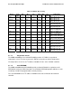
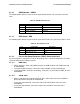
Table 43. LED Function
Status LED Condition Definition
On HDD Active
Blink (0.5s on 0.5s off, 50% duty
cycle of a 1s)
Spin up/spin down(SAS HDD)
Green
Blink (1s on 1s off, 50% duty
cycle of a 2s)
Formating(SAS HDD)
Amber on On HDD Fail
Blink Rebuild
Note:
For SAS drives, Green LED will be on when drive is installed and ready. For SATA drives Green LED will be off when
drive is installed and ready.