
Technical Product Specification


Intel® Local Control Panel TPS Appendix A
Revision 1.2
Intel order number C96442-003
35
Item
Feature
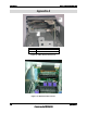
A
4-pin IPMI Interface Header
Figure 18. SKU3 Internal Connector
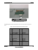
The following tables provide the pin definitions for three of the four internal connectors on
SKU1.
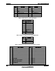
Table 5. SKU1 Internal 50-pin Front Panel Interface Header
Pin #
Description
Pin #
Description
1
P5V_STBY
26
Not used
2
P5V_STBY
27
NIC1_LINK_LED_R_L
3
P5V
28
NIC1_ACT_LED_L
4
HDD_LED_ACT_R_L
29
GND
5
FP_SYS_FLT_LED1_R_L
30
FP_NMI_BTN_L
6
RST_P6_PWRGOOD
31
EMP_INUSE_L
7
FP_SYS_FLT_LED2_R_L
32
EMP_DSR2_L
8
PWR_LED_5VSB
33
EMP_SOUT2
9
FAULT_LED_5VSB
34
EMP_SIN2
10
FP_PWR_LED_R_L
35
EMP_CTS2_L
11
HDD_LED_P3V3_A
36
EMP_RST2_L
12
IPMB_5VSB_SDA
37
EMP_DCD2_L
13
GND
38
EMP_DTR2_L
14
IPMB_5VSB_SCL
39
1_WIRE_BUS
15
FP_ID_LED_R_L
40
VGA_INUSE_L
16
FP_PWR_BTN_L
41
GND
17
NIC2_LINK_LED_R_L
42
VGA_VSYNC_FP_L
18
HDD_FAULT_LED_R_L
43
GND