
Technical Product Specification


Intel® Server Chassis SC5400 5U Kit TPS Hot Swap Hard Disk Drive Bays
Revision: 1.0
69
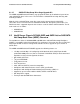
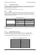
6.2.3 External Memory Device
The 4HDD and 6HDD active SAS/SATA HSBP contains a non-volatile 8Mbit Serial SPI FLASH
Memory for Boot and Run-Time/Configuration code storage. The device resides on the SPI
interface of VSC7161* SAS Expander.
The Serial SPI Flash memory operates from the 3.3V rail.
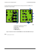
6.2.4 LEDs
The 4 and 6 HDD Active SAS/SATA HSBP contains a green STATUS LED and amber FAULT
LED for each of the six hard disk drives. The STATUS LED is driven by the SAS/SATA hard
disk drive itself. The FAULT LED is driven by the VSC410* controller whenever a condition, as
defined by the firmware, is detected.
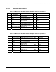
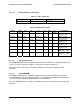
Table 56. LED Function
Status LED Condition Definition
On HDD Active
Blink (0.5s on 0.5s off, 50% duty
cycle of a 1s)
Spin up/spin down(SAS HDD)
Green
Blink (1s on 1s off, 50% duty
cycle of a 2s)
Formating(SAS HDD)
Amber On On HDD Fail
Blink Rebuild
Note:
For SAS drives, Green LED will be on when drive is installed and ready. For SATA drives Green LED will be off when
drive is installed and ready.
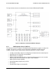
6.2.5 SAS/SATA Drive Connectors
The 4HDD and 6HDD active SAS/SATA HSBP provides four or six 22-pin SAS/SATA
connectors for hot swap hard disk drives supporting a 1.5GHz and 3.0GHz transfer rate.
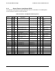
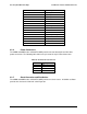
The following table defines the pin-out of the 22-pin SAS/SATA Drive Connector:
Table 57. 22-pin SAS/SATA Connector Pin-out
Connector Contact Number Signal Name
S1 GND
S2 DRVnA_RX_P
S3 DRVnA_RX_N
S4 GND
S5 DRVnA_TX_N
S6 DRVnA_TX_P
S7 GND