
Technical Product Specification


Intel® Server Chassis SC5400 5U Kit TPS Hot Swap Hard Disk Drive Bays
Revision: 1.0
59
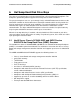
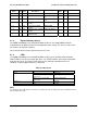
6.1.10 SGPIO Header - SGPIO
The following table defines the pin-out of the 4-pin SGPIO Header. This connector is black in
color.
Table 48. SGPIO Header Pin-out
Pin Signal Name Description
1 SGPIO_CLK Clock
2 SGPIO_LOAD Load
3 SGPIO_DATAOUT0 DATAIN
4 SGPIO_DATAOUT1 DATAOUT
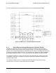
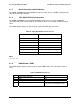
6.1.11 SES Header - SES
The following table defines the pin-out of the 3-pin SES Header. This connector is white in color.
Table 49. SES Header Pin-out
Pin Signal Name Description
1 SMB_HBA_I2C_DAT Data
2 GND Ground
3 SMB_HBA_I2C_CLK Clock
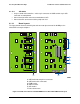
6.1.12 Passive Hot Swap Backplane (HSBP) Cables Explained
Passive backplanes ship with three cables. Depending on the intended configuration, the cables
should be utilized in the following manner:
6.1.12.1 IPMB Cable
Always Installed – white 4-pin IPMB connector on HSBP to white 4 pin IPMB connector
on motherboard
If using one HSBP (Primary), connect the cable to HSBP_A on the motherboard
If using two HSBPs (Primary & Secondary), connect the second cable to HSBP_B on the
motherboard
6.1.12.2 SGPIO Cable
Always used when using onboard SATA or SAS – black 4-pin connector on HSBP to
black 4-pin SGPIO connector on motherboard
If using the onboard SATA, connect the cable to the SATA GPIO connector on the
motherboard
If using the onboard SAS, connect the cable to the SAS GPIO connector on the
motherboard