
Technical Product Specification


Intel® Server Chassis SC5400 5U Kit TPS Chassis Power Subsystem
Revision: 1.0
43
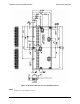
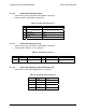
From
Length For Revision S0
Only (mm)
Connector
#
Number of
Pins
Description
Power supply cover exit hole
565
P10 4
Peripheral Power
Connector
Extension
75
P11 4
Peripheral Power
Connector
Power supply cover exit hole 565 P12 5
Right-angle SATA Power
Connector
Extension 75 P13 5 SATA Power Connector
Power supply cover exit hole 755 P14 2x2 12V4 Power Connector
Power supply cover exit hole 450 P15 1x5 Signal Connector
Note:
Floppy drive not supported by the Intel® Server Board S5000PSL, Intel® Server Board S5000XSL and Intel® Server
Board S5000XVN.
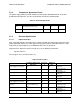
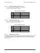
5.3.3.2 Server Board Power Connector (P1)
Connector housing: 24-Pin Molex Mini-Fit Jr. 39-01-2245 or equivalent
Contact: Molex Mini-Fit, HCS, Female, Crimp 44476 or equivalent
Table 29. Server Board Power Connector
Pin Signal 18 AWG Color Pin Signal 18 AWG Color
1 +3.3VDC
12
Orange 13 +3.3VDC Orange
2 +3.3VDC Orange 14 -12VDC Blue
3 COM Black 15 COM Black
4
+5VDC
1
Red 16 PSON
#
Green
5 COM Black 17 COM Black
6 +5VDC Red 18 COM Black
7 COM Black 19 COM Black
8 PWR OK Gray 20 Reserved N.C.
9 5 VSB Purple 21 +5VDC Red
10 +12V3 Yellow 22 +5VDC Red
11 +12V3 Yellow 23 +5VDC Red
12 +3.3VDC Orange 24 COM Black
Notes:
Remote Sense wire double crimped
If the signal connector is not present, the 3.3V remote sense wire will be double crimped into pin 1 in the baseboard
power connector (P1)