
Technical Product Specification
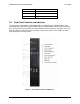

Intel® Server Chassis SC5400 5U Kit TPS Front Panel
Revision: 1.0
17
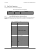
3.3.1 Power / Sleep LED
The green power LED is active when system DC power is on. The power LED is controlled by
the BIOS. The power LED reflects a combination of the state of system (DC) power and the
system ACPI state. Table 8 shows the states that can be assumed
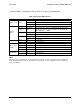
Table 8. Power LED Operation.
State Power Mode LED Description
Power Off Non-ACPI Off System power is off, and the BIOS has not initialized the chipset.
Power On Non-ACPI On
System power is on, but the BIOS has not yet initialized the
chipset.
S5 ACPI Off Mechanical is off, and the operating system has not saved any
context to the hard disk.
S4 ACPI Off Mechanical is off. The operating system has saved context to the
hard disk.
S3-S1 ACPI Slow blink DC power is still on. The operating system has saved context and
entered into a level of low-power state.
S0 ACPI Steady on System and the operating system are up and running.
3.3.2 System Status LED
The system status LED is a bi-color LED. Green (status) is used to show a normal operation
state or a degraded operation. Amber (fault) shows the platform hardware state and overrides
the green status.
When the server is powered down (transitions to the DC-off state or S5), the BMC is still on
standby power and retains the sensor and front panel status LED state established prior to the
power-down event.
When AC power is first applied to the system and 5V-STBY is present, the BMC controller on
the server board requires 15-20 seconds to initialize. During this time, the System Status LED
will blink, alternating between Amber and Green. In addition, the Power Button functionality of
the Control Panel is disabled, preventing the server from powering up. Once BMC initialization
has completed, the Status LED will stop blinking and the Power Button functionality is restored
and can be used to turn on the server.
3.3.2.1 Critical Conditions
A critical condition is defined as any critical or non-recoverable threshold crossing associated
with the following events:
DIMM failure when there is one DIMM present, no good memory present
Run-time memory uncorrectable error in non-redundant mode
Processor 1 missing
Temperature (CPU, memory, critical threshold crossed)
No power good – power fault
Processor configuration error