
Technical Product Specification


Physical and Electrical Description Intel® Local Control Panel TPS
Revision 1.2
Intel order number C96442-003
6
2.2 System Components and Functions
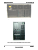
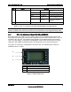
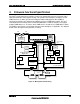
The figure below shows the standard Intel
®
Local Control Panel buttons and configuration. The
components shown in the following diagram are included in both SKU1 and SKU2. Additional
components that are specific to each SKU are detailed in the subsections below.
Item
Feature
Description
A
LCD display
Video display
B
Scroll up button
Press to scroll up on the LCD
C
Scroll down button
Press to scroll down on the LCD
D
Back button
Press to move to the previous LCD screen.
E
Select button
Press to enter a command or select an option on the LCD.
F
System ID LED (Blue)
Helps identify the system via server management
G
System Power LED (Green)
Indicates system power status.
Off
Power off
ACPI: No
On
Power on
ACPI: No
Off
S4* / S5
ACPI: Yes
Blinking
S1*
ACPI: Yes
On
S0
Yes
H
System Power button
Toggles system power
I
System Status/Fault LED
(Green/Amber)
Indicates system status.
Off
Not ready
AC power off, POST error
Green, On
Ready
System booted and ready
Green, Blinking
Degraded
Processor or DIMM
disabled
Amber, On
Critical Alarm
Critical power supply,
blower, voltage, or
temperature failure
Amber, Blinking
Non-Critical
Alarm
Redundant power supply or
blower failure.
Non-critical blower, voltage,
or temperature failure.
J, K
LAN1, LAN2 Status LEDs
(Green)
Indicates LAN activity status.
Off
Idle
On
Inactive
No access
Blinking
Active
Access
L
Hard Drive Status LED
Indicates hard drive activity and fault status.