Intel® Entry Server Chassis SC5275-E User Guide A Guide for Technically Qualified Assemblers of Intel® Identified Subassemblies/Products Order Number: C50277-001
Disclaimer Information in this document is provided in connection with Intel® products. No license, express or implied, by estoppel or otherwise, to any intellectual property rights is granted by this document.
Preface Preface About this Manual ® Thank you for purchasing and using the Intel Entry Server Chassis SC5275-E. This manual is written for system technicians who are responsible for troubleshooting, upgrading, and reparing this server chassis. This document provides a brief overview of the features of the board/chassis, a list of accessories or other components you may need, troubleshooting information, and instructions on how to add and replace components on the Intel® Entry Server Chassis SC5275-E.
Preface Additional Information and Software If you need more information about this product or information about the accessories that can be used with this server chassis, use the following resources: For in-depth technical information about this product, including BIOS settings and chipset information Intel® Server Chassis SC5275-E Technical Product Specification at http://support.intel.com/support/motherboards/server/chassis/ SC5275E.
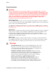
Preface Safety Information WARNING Before working with your server product, whether you are using this guide or any other resource as a reference, pay close attention to the safety instructions. You must adhere to the assembly instructions in this guide to ensure and maintain compliance with existing product certifications and approvals. Use only the described, regulated components specified in this guide.
Preface strap attached to chassis groundany unpainted metal surfaceon your server when handling parts. ESD and handling boards: Always handle boards carefully. They can be extremely sensitive to ESD. Hold boards only by their edges. After removing a board from its protective wrapper or from the server, place the board component side up on a grounded, static free surface. Use a conductive foam pad if available but not the board wrapper. Do not slide board over any surface.
Preface 5. 6. Provide some electrostatic discharge (ESD) protection by wearing an antistatic wrist strap attached to chassis ground of the system—any unpainted metal surface—when handling components. Do not operate the system with the chassis covers removed. After you have completed the six SAFETY steps above, you can remove the system covers. To do this: 1. 2. 3. Unlock and remove the padlock from the back of the system if a padlock has been installed. Remove and save all screws from the covers.
Preface Benutzer können am Netzgerät dieses Produkts keine Reparaturen vornehmen. Das Produkt enthält möglicherweise mehrere Netzgeräte. Wartungsarbeiten müssen von qualifizierten Technikern ausgeführt werden. Versuchen Sie nicht, das mitgelieferte Netzkabel zu ändern oder zu verwenden, wenn es sich nicht genau um den erforderlichen Typ handelt. Ein Produkt mit mehreren Netzgeräten hat für jedes Netzgerät ein eigenes Netzkabel.
Preface durch denselben oder einen entsprechenden, vom Hersteller empfohlenen Batterietyp ersetzt werden. Entsorgen Sie verbrauchte Batterien den Anweisungen des Herstellers entsprechend. Das System wurde für den Betrieb in einer normalen Büroumgebung entwickelt.
Preface CONSIGNES DE SÉCURITÉ -Lorsque vous ouvrez le boîtier pour accéder à l’intérieur du système, suivez les consignes suivantes: 1. 2. 3. 4. 5. 6. Mettez hors tension tous les périphériques connectés au système. Mettez le système hors tension en mettant l’interrupteur général en position OFF (bouton-poussoir). Débranchez tous les cordons d’alimentation c.a. du système et des prises murales. Identifiez et débranchez tous les câbles reliés aux connecteurs d’E-S ou aux accès derrière le système.
Preface télécommunications de votre modem durant un orage. Muni d'une prise murale correctement mise à la terre. Suffisamment spacieux pour vous permettre d'accéder aux câbles d'alimentation (ceux-ci étant le seul moyen de mettre le système hors tension). Instrucciones de seguridad importantes Lea todas las declaraciones de seguridad y precaución de este documento antes de realizar cualquiera de las instrucciones. Vea Intel Server Boards and Server Chassis Safety Information en en http://support.intel.
Preface 2. 3. 4. 5. sistema. Compruebe que los cables, las placas adicionales y otros componentes se hayan instalado correctamente. Incorpore las tapas al chasis mediante los tornillos extraídos anteriormente, tensándolos firmemente. Inserte el bloqueo de seguridad en el sistema y bloquéelo para impedir que pueda accederse al mismo sin autorización. Conecte todos los cables externos y los cables de alimentación CA al sistema.
Preface PASSI DI SICUREZZA: Qualora si rimuovano le coperture del telaio per accedere all’interno del sistema, seguire i seguenti passi: 1. 2. 3. 4. 5. 6. Spegnere tutti i dispositivi periferici collegati al sistema. Spegnere il sistema, usando il pulsante spento/acceso dell’interruttore del sistema. Togliere tutte le spine dei cavi del sistema dalle prese elettriche. Identificare e sconnettere tutti i cavi attaccati ai collegamenti I/O od alle prese installate sul retro del sistema.
Preface Intel® Entry Server Chassis SC5275-E User Guide xiv
Contents Contents Warnings ......................................................................................................... v 1 Chassis Description....................................................................................... 1 Kit Contents............................................................................................................................. 1 Feature Summary ............................................................................................................
Contents Replacing a Front System Fan..................................................................................... 31 Replacing a Rear System Fan ..................................................................................... 32 Replacing the Power Supply ................................................................................................. 33 Replacing the Front Panel Board ..........................................................................................
Contents Figure 6. Removing the 3.5-inch EMI Shield ............................................................................. 14 Figure 7. Installing a Floppy Drive ............................................................................................. 15 Figure 8. Removing EMI Shields ............................................................................................... 16 Figure 9. Slide Rails..............................................................................................
Contents Intel® Entry Server Chassis SC5275-E User Guide xviii
1 Chassis Description 1 Chassis Description Kit Contents The chassis subassembly kit includes this product guide and a box that includes two pair of 5.25inch external drive rails, four different types of mounting screws, and two brackets for the optional SCSI hot-swap hard drive bay (SCSI hot-swap hard drive bay not included). A B C TP00835 A. Flat head 6-32 x 5mm [.200] C. Hex head 6-32 x 6mm [.256] B. Flat head M3 x 5mm [.200] Figure 1. Screw Description Feature Summary Table 1.
1 Chassis Description Chassis Front View A B C D E F TP00053 A. B. C. D. E. F. Front panel controls and indicators 5.25-inch removable media drive bays 3.
1 Chassis Description Front Panel Controls and Indicators A B C D E F H G I TP00080 A. B. C. D. E. F. G. H. I. Power / sleep LED Power button NMI button Reset button Sleep button NIC 1 activity LED NIC 2 activity LED Hard drive activity LED Status LED * Some items may not be supported by all server boards. Table 2.
1 Chassis Description Chassis Rear View A B C D E F A. B. C. D. E. F. G. H. I. J. K. TP00834 Alternate Serial B port knockout Alternate ICMB or external SCSI knockout AC input power connector Power supply Fan I/O ports* Expansion slot covers ICMB or external SCSI knockout Serial B port knockout Location to install padlock loop Chassis intrusion switch * Items shown may be different in your chassis.
1 Chassis Description Peripherals 5.25-inch Removable Media Drive Bays The upper bays are designed for removable media peripherals. You can install up to two half-height peripherals. 3.5-inch Hard Drive Bays The chassis supports up six drives depending on the power budget. The drives are installed into a removable hard drive bay cage that is located beneath the floppy drive bay. The hard drive bay cage is not externally accessible. Optional 3.
1 Chassis Description Power Supply The 600-Watt PFC non-redundant power supply is auto ranging for either 100-127 VAC or 200-240 VAC operation. Checking the Power Cord WARNING Do not attempt to modify or use a supplied AC power cord if it is not the exact type required. The power supply cord is the main disconnect device to mains (AC power). The socket outlet shall be installed near the equipment and shall be readily accessible.
1 Chassis Description Mechanical Locks The front bezel has a two-position lock to prevent access to the hard drives and the interior of the chassis. A padlock loop is included with the chassis and can be installed at the rear of the chassis. A B TP00055 A. B. Location to install padlock loop Front bezel locked position Figure 2.
1 Chassis Description Intel® Entry Server Chassis SC5275-E User Guide 8
2 Setting Up the Chassis 2 Setting Up the Chassis This chapter describes how to set the server up for the first time. With the exception of replacing the front panel board (discussed in Chapter 4), it is necessary to remove only the left access cover, not the cover at the right.
2 Setting Up the Chassis Warnings and Cautions These warnings and cautions apply whenever you remove the access cover(s) to access components inside the server. Only a technically qualified person should integrate and configure the server. WARNINGS The power button on the front panel DOES NOT turn off the AC power. To remove power from server, you must unplug the AC power cord from the wall outlet or the chassis.
2 Setting Up the Chassis Remove the Access Cover Observe the safety and ESD precautions at the beginning of this chapter. For ease of installation, before beginning lay the chassis on its right side, with the left access cover facing up. 1. If the shipping screws are installed, remove them (number 1 in the figure below). 2. Slide the thumb latches to the left to the unlocked position (number 2 in the figure). 3. Slide the cover backward a short distance, until it stops (number 3 in the figure). 4.
2 Setting Up the Chassis Remove the Front Bezel 1. Pull the left side of the bezel forward to disengage the tabs (facing up in the following figure). See number 1 in the figure. 2. Remove the bezel from the tabs at the right side of the chassis (facing down in the following figure). See number 2 in the figure. 1 1 2 2 TP00086 Figure 4.
2 Setting Up the Chassis Install the I/O Shield ✏ NOTE An ATX 2.03-compliant I/O shield should be provided with your server board. The shield is required by Electromagnetic Interference (EMI) regulations. It minimizes EMI and ensures proper cooling of the server. The shield fits the rectangular opening near the power supply in the back of the chassis. The shield has cutouts that match the external I/O connectors (e.g., keyboard and mouse). 1.
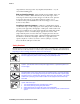
2 Setting Up the Chassis Install the Server Board Standoffs and Bumpers The location of the standoffs and bumpers varies by server board. Read and follow the instructions provided with the server board Quick Start User’s Guide for proper standoff and bumper placement. Install a 3.5-inch Floppy Drive 1. Use the finger cutouts on the EMI shield to grasp the shield and remove it from the chassis. 2. Remove the plastic filler panel from the bezel. TP00058 Figure 6. Removing the 3.5-inch EMI Shield 5.
2 Setting Up the Chassis 8. Slide the drive into the chassis. When properly positioned, the holes in the side of the drive align with the threaded holes in the chassis frame. 9. Secure the drive to the side of the chassis with two screws. Note that only two screws are required at the left side of the chassis to secure the device to the chassis. Tighten the screws firmly. 10. Connect the data and power cables to the drive. B TP00060 Figure 7.
2 Setting Up the Chassis IDE Requirements If no drives are present on an IDE channel, the cable must be removed. If only one drive is installed, it should be connected at the end of the cable. ✏ NOTE To disable the IDE controller: If you plan to disable the IDE controller to reuse the interrupt for that controller, you must physically unplug the IDE cable from the board connector if a cable is present. Simply disabling the drive by configuring the SSU option does not make the interrupt available.
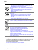
2 Setting Up the Chassis 3. 4. 5. 6. Remove the drive from its protective wrapper and place it on an antistatic surface. Record the drive model and serial numbers in your equipment log. Set any jumpers or switches on the drive according to the drive manufacturer’s instructions. Using four screws of the appropriate size and length, attach two slide rails to the drive. Note that the left and right rails mirror each other.
2 Setting Up the Chassis 7. Position the drive so the slide rails engage in the chassis bay guide rails. Push the drive into the bay until the slide rails are flush with the chassis. 8. Use two screws for each slide rail to attach the device at the front of the chassis. 9. Connect the data and power cables to the drive. The connectors are keyed and can be inserted in only one way. TP00065 Figure 10.
2 Setting Up the Chassis Install the Server Board 1. Remove and save the four screws that secure the drive cage to the chassis. Two screws are at the front of the chassis and two are at the side of it. 2. Slide the drive cage out of the chassis. You may need to push the cage out from the inside of the chassis. TP00062 Figure 11. Removing a Drive Cage 3. For additional information, read and follow the instructions provided with the server board Quick Start User’s Guide.
2 Setting Up the Chassis Installing 3.5-inch Hard Drive Six 3.5-inch half-height bays provide space for hard drives. For proper cooling, always install drives into the four center bays first ✏ NOTE The drive bay cage can only be fully populated with six hard drives if the power budget has the capacity for it, such as when only a single processor is used. Before installing more than four hard drives, calculate the power used by each installed device and compare it to the allowed power budget.
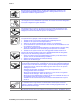
2 Setting Up the Chassis 6. Slide the drive into the back of the drive cage along the rails in the cage. Install the drive with the component side facing down. The drive power and data connectors must face out the open side of the cage. 7. Push the drive in until the drive connectors are flush with the rear of the cage. 8. Line up the screws holes in the sides of the cage with the screw holes in the drive. 9. Use four screws (screw A), attach the drive to the cage. A A B TP00063 A. B. Screw tabs.
2 Setting Up the Chassis 10. After all drives are installed into the cage, slide the cage into the chassis, making sure the arrow and the screw tabs point toward the top of the chassis. 11. Insert and tighten the four screws removed in Step 1. 12. Attach data and power cables to the drive(s). A B TP00066 A. B. Data and power cables Screw tabs. Point toward top of chassis. Figure 13.
2 Setting Up the Chassis Connect Cables to the Server Board See your server board product guide or Quick Start User’s Guide for connector locations. 1. Connect the power cables to the server board. • The large plug labeled P1 plugs into the main power connector on the server board • The plug labeled P2 plugs into the +12V CPU Power connector on the server board 2. Connect the front panel cable to the server board. 3. Connect the USB cable to the server board. 4. Connect the fan cables to the server board.
2 Setting Up the Chassis Installing an Add-in Board You may want to install an operating system before installing any add-in boards. If so, skip this step and return to it when you are ready. CAUTIONS Do not overload the server board by installing add-in boards that draw excessive current. Add-in boards can be extremely sensitive to ESD and always require careful handling.
2 Setting Up the Chassis A B C OM11961 A. Snap-in slot cover B. Tapered foot C. Slot Figure 14.
2 Setting Up the Chassis Install the Front Bezel 1. Angle the bezel toward the chassis as shown by number 1 in the figure below. 2. Insert the latches on the right side of the bezel (facing down in the figure below) into the corresponding slots in the chassis. See number 2 in the figure. 3. Rotate the left side of the bezel (facing up in the figure below) over the side of the chassis to engage the two tabs. See number 3 in the figure.
2 Setting Up the Chassis Install the Access Cover 1. Place the cover so the tabs on the cover fit into the slots on the server. The cover should be flush against the chassis. 2. Slide the cover forward until it stops (letter A in the figure below). 3. Slide the two thumb latches to the right to the “lock” position (letter B in figure). For additional security, you can also replace the shipping screws if desired. A B B TP00067 Figure 16.
3 Maintaining Your Server 3 Maintaining Your Server This chapter describes how to replace components in your server after it has been set up. Tools and Supplies Needed Phillips (cross head) screwdriver (#2 bit) Small flathead screwdriver Antistatic wrist strap (recommended) Needle-nosed pliers Safety: Before You Remove the Access Cover(s) Before removing the access cover for any reason, observe these safety guidelines: 1. Turn off all peripheral devices connected to the server. 2.
3 Maintaining Your Server CAUTIONS ESD can damage disk drives, boards, and other parts. Perform all procedures in this chapter only at an ESD workstation. If one is not available, provide some ESD protection by wearing an antistatic wrist strap attached to chassis groundany unpainted metal surfaceon your server when handling parts. Always handle boards carefully. They can be extremely sensitive to ESD. Hold boards only by their edges. Do not touch the connector contacts.
3 Maintaining Your Server Replacing Fans The chassis contains two replaceable system fans. The power supply fan(s) are not replaceable. Your replacement fan should be the same size and type as the fan you are removing. Replacing a Front System Fan Standard Hard Drive Bay Cage The front system fan is located inside the hard drive bay cage. To replace it, the cage must be removed. It is not necessary to remove the hard drives from the cage. 1. Remove the left access cover. 2. Remove the bezel. 3.
3 Maintaining Your Server 9. Slide the new fan in through the fan opening. Make sure the airflow is towards the server board. This means the label should face the server board. 10. Replace the nylon rivets to attach the fan to the hard drive bay cage. 11. Replace the hard drive bay cage in the chassis. Make sure the fan opening faces the bottom of the chassis. 12. Connect the fan cable to the server board and reconnect the hard drives. 13. Replace the bezel. 14. Replace the access cover.
3 Maintaining Your Server Replacing the Power Supply WARNINGS Hazardous conditions, power supply: Hazardous voltage, current, and energy levels are present inside the power supply. There are no user-serviceable parts inside it; servicing should be done by technically qualified personnel. To replace the power supply: 1. Disconnect the A/C power from the power supply. 2. Remove the left access cover. 3. Disconnect all of the power cables inside the chassis. 4.
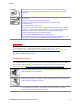
3 Maintaining Your Server Replacing the Front Panel Board 1. 2. 3. 4. Remove the left access cover. Remove the bezel. Remove the two screws at the rear of the chassis that hold the right access cover in place. Remove the right access cover. A rectangular opening at the right side of the chassis provides access to the front panel board. B A TP00069 A. Right side of chassis, access cover removed B. Access to Front Panel Board Figure 19. Front Panel Board Access 5.
3 Maintaining Your Server 8. Slide the end of front panel board cable through the front panel opening and attach it to the new front panel board. Attach the cable before installing the new front panel board into the chassis to ensure the cable pins line up correctly. TP00082 Figure 21. Attaching the Front Panel Cable 9. Place the new front panel board in the chassis. 10. Insert and tighten the three screws removed earlier. TP00083 Figure 22. Inserting the Front Panel Board 11.
3 Maintaining Your Server Replacing the USB Cable 1. 2. 3. 4. 5. ✏ Remove the left access cover. Remove the bezel. Disconnect the existing USB cable from the server board. Disconnect the bracket the attaches the USB cable to the front of the chassis. Remove all add-in boards. NOTE When removing a full-length add-in card, you must pull back on the latch on the plastic card guide at the front of the chassis to release the card from the card guide. 6.
3 Maintaining Your Server Intel® Entry Server Chassis SC5275-E User Guide 37
4 Technical Reference 4 Technical Reference Power Supply Specifications 600 Watt Single Power Supply Input Voltages 600 Watt Power Supply 100-127 V∼ at 50/60 Hz; 6.5 A max. 200-240 V∼ at 50/60 Hz; 3.2 A max. 600 Watt Single Power Supply Output Voltages 600 Watt Power Supply The table below lists the total wattage available from the power subsystem for each voltage. If you configure your system heavily, ensure that your loads do not exceed the combined total wattage of 600 Watts.
4 Technical Reference System Environmental Specifications Table 5. Environmental Specifications Temperature Non-operating Operating Humidity Non-operating –40 ° to 70 °C. 5 ° to 35 °C; derated 0.5 °C for every 1000 ft (305 m) to a maximum of 10,000 ft. 95% relative humidity (non-condensing) at 30 °C. Shock Operating Packaged 2.0 g, 11 msec, 1/2 sine Operational after an 18” free fall. Acoustic noise 50 dBA in a typical office ambient temperature (65-75 °F).
Equipment Log and Worksheets Equipment Log and Worksheets Equipment Log Use the blank equipment log provided here to record information about your server. You will need some of this information when you run the SSU. Item Manufacturer Name and Model Number Serial Number Date Installed Chassis Server Board Processor Speed and Cache Memory Video Display Keyboard Mouse Diskette Drive A CD-ROM Drive Additional 5.
Equipment Log and Worksheets Equipment Log (continued) Item Manufacturer Name and Model Number Serial Number Intel® Entry Server Chassis SC5275-E User Guide Date Installed 42
Equipment Log and Worksheets Current Usage Calculating Power Usage The total combined wattage for your configuration must be less than the wattage rating for your power supply. Use the two worksheets in this section to calculate the total used by your configuration. For current and voltage requirements of add-in boards and peripherals, see your vendor documents. Worksheet, Calculating DC Power Usage Table 6. Power Usage Worksheet 1 Current (maximum) at voltage level: Device +3.
Equipment Log and Worksheets Worksheet, Total Combined Power Used by the Server 1. From the previous worksheet, enter the total current for each column. 2. Multiply the voltage by the total current to get the total wattage for each voltage level. 3. Add the total wattage for each voltage level to arrive at the total combined power usage for the power subsystem. Table 7. Power Usage Worksheet 2 Voltage level and total current (V X A = W) Total Watts for each voltage level (+3.
Regulatory and Compliance Information Regulatory and Compliance Information Product Regulatory Compliance Product Safety Compliance The Intel® Entry Server Chassis SC5275-E complies with the following safety requirements: UL60950 – CSA 60950(USA / Canada) EN60950 (Europe) IEC60950 (International) CB Certificate & Report, IEC60950 (report to include all country national deviations) GS License (Germany) GOST R 50377-92 - License (Russia) Belarus License (Belarus) Ukraine License (Ukraine) CE - Low Voltage Di
Regulatory and Compliance Information GB 17625 - (Harmonics) CNCA Certification (China) Certifications / Registrations / Declarations UL Certification (US/Canada) CE Declaration of Conformity (CENELEC Europe) FCC/ICES-003 Class A Attestation (USA/Canada) VCCI Certification (Japan) C-Tick Declaration of Conformity (Australia) MED Declaration of Conformity (New Zealand) BSMI Certification (Taiwan) GOST R Certification / License (Russia) Belarus Certification / License (Belarus) RRL Certification (Korea) IRA
Regulatory and Compliance Information Regulatory Compliance Country BSMI Certification Number & Class A Warning Taiwan GOST R Marking Russia RRL MIC Mark Korea China Compulsory Certification Mark China Marking Electromagnetic Compatibility Notices FCC (USA) This device complies with Part 15 of the FCC Rules.
Regulatory and Compliance Information This equipment has been tested and found to comply with the limits for a Class A digital device, pursuant to Part 15 of the FCC Rules. These limits are designed to provide reasonable protection against harmful interference in a residential installation. This equipment generates, uses, and can radiate radio frequency energy and, if not installed and used in accordance with the instructions, may cause harmful interference to radio communications.
Regulatory and Compliance Information VCCI (Japan) English translation of the notice above: This is a Class A product based on the standard of the Voluntary Control Council for Interference (VCCI) from Information Technology Equipment. If this is used near a radio or television receiver in a domestic environment, it may cause radio interference. Install and use the equipment according to the instruction manual.
Regulatory and Compliance Information Regulated Specified Components To maintain the UL listing and compliance to other regulatory certifications and/or declarations, the following regulated components must be used and conditions adhered to. Interchanging or use of other component will void the UL listing and other product certifications and approvals. Updated product information for configurations can be found on the Intel Server Builder Web site at the following URL: http://channel.intel.
Getting Help Getting Help World Wide Web http://support.intel.com/support/motherboards/server/chassis/SC5275E Telephone All calls are billed US $25.00 per incident, levied in local currency at the applicable credit card exchange rate plus applicable taxes. (Intel reserves the right to change the pricing for telephone support at any time without notice). In U.S.
Getting Help In Latin America Brazil 001-916-377-0180 Mexico contact AT&T USA by dialing 001-800-4624240; once connected, dial 800-843-4481 Colombia contact AT&T USA by dialing 01-800-9110010; once connected, dial 800-843-4481 Costa Rica contact AT&T USA by dialing 0-800-0-114114; once connected, dial 800-843-4481 Panama contact AT&T USA by dialing 00-800-0010109; once connected, dial 800-843-4481 Chile (Easter Island) contact AT&T USA by dialing 800800-311; once connected, dial 800-843-4481 Chile (Mainlan
Warranty Warranty Limited Warranty for Intel® Chassis Subassembly Products Intel warrants that the Products (defined herein as the Intel® chassis subassembly and all of its various components and software delivered with or as part of the Products) to be delivered hereunder, if properly used and installed, will be free from defects in material and workmanship and will substantially conform to Intel’s publicly available specifications for a period of three (3) years after the date the Product was purchased f
Warranty Warranty Limitations and Exclusions These warranties replace all other warranties, expressed or implied including, but not limited to, the implied warranties of merchantability and fitness for a particular purpose. Intel makes no expressed warranties beyond those stated here. Intel disclaims all other warranties, expressed or implied including, without limitation, implied warranties of merchantability and fitness for a particular purpose.
Warranty How to Obtain Warranty Service To obtain warranty service for this Product, you may contact Intel or your authorized distributor. North America and Latin AmericaTo obtain warranty repair for the product, please go to the following Web site to obtain instructions: http://support.intel.com/support/motherboards/draform.htm In Europe and in AsiaContact your original authorized distributor for warranty service.