SBC-780 Pentium III Socket 370 Full-Size CPU Card With LCD, Ethernet, Audio, PCI/104 & CompactFlashTM SBC-780 Rev A Manual 4 th Ed. Feb.
F u l l-S i z e C P U C a r d SBC-7 8 0 Copyright Notice This document is copyrighted, 2004. All rights are reserved. The original manufacturer reserves the right to make improvements to the products described in this manual at any time without notice. No part of this man ual may be reproduced, copied, translat ed, or transmitted in any form or by any means without the prior written permission of the original manufacturer. Information provided in this manual is intended to be accurate and reliable.
F u l l-S i z e C P U C a r d SBC-7 8 0 Acknowledgments Award is a trademark of Award Software International, Inc. CompactFlash is a registered trademark of the Compact Flash Association. Intel®, Pentium®!!!, and Celeron® are trademarks of Intel® Corporation. Microsoft Windows® is a registered trademark of Microsoft Corp. ITE is a trademark of Integrated Technology Express, Inc. IBM, PC/AT, PS/2, and VGA are trademarks of International Business Machines Corporation.
F u l l-S i z e C P U C a r d SBC-7 8 0 Packing List Before you begin installing your card, please make sure that the following materials have been shipped: • 1 SBC-780 Full-Size CPU Card • 1 Quick Installation Guide • 1 CD -ROM for manual (in PDF format) and drivers • 1 HDD Cable (ATA 66/100) • 1 FDD Cable • 1 Audio and COM Port Cable with bracket • 1 LPT and COM Port Cable with bracket • 1 Y -Cable (Keyboard and Mouse) • 1 USB Cable with bracket • 1 Jumper Cap • 1 Short Copper Kit
F u l l-S i z e C P U C a r d SBC-7 8 0 Contents Chapter 1 General Information 1.1 Introduction ..................................................................................1-2 1.2 Features .........................................................................................1-3 1.3 Specifications ................................................................................1-4 Chapter 2 Quick Installation Guide 2.1 Safety Precautions ............................................................
F u l l-S i z e C P U C a r d SBC-7 8 0 2.18 SIR Connectors (CN6) ..............................................................2-16 2.19 USB Connectors (CN8/CN9) ..................................................2-16 2.20 LPT Port Connector (CN10) ....................................................2-17 2.21 COM2 RS-232/422/485 Serial Port Connector (CN11).......2-17 2.22 Floppy Connector (CN12) ........................................................2-18 2.23 COM1 RS-232 Serial Port Connector (CN13)....
F u l l-S i z e C P U C a r d SBC-7 8 0 3.2.6 Clk/Voltage Setup.................................................................3-31 3.2.7 Exit Setup..............................................................................3-32 Chapter 4 Driver Installation..........................................4-1 Appendix A Programming the WatchDog Timer..A-1 Appendix B CFD Cover Installation Guide.. … … … … .B-1 B.1 How to install the CompactFlash cover............................... B-2 B.
F u l l-S i z e C P U C a r d SBC-7 8 0 1 Chapter General Information Chapter 1 General Information 1- 1
F u l l-S i z e C P U C a r d SBC-7 8 0 1.1 Introduction The all-in-one SBC-780 single board computer series is designed for embedded applications where full features and performance are major concerns. The various CPU options support Intel Pentium III, Celeron (up to Tualatin 1.4GHz) and VIA C3 processors (up to 1.1GHz), SBC-780 series brings with its significant gains in performance. SBC-780 series is powered by with the VIA Twister-T system chipset.
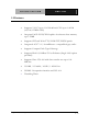
F u l l-S i z e C P U C a r d SBC-7 8 0 1.2 Features • Supports VIA C3 up to 1.1GHz & Intel CPU up to 1.4GHz (66/100/133MHz FSB) • Integrated AGP 4X 2D/3D Graphics Accelerator share memory up to 32MB • Supports CRT and 36-bit TTL/LVDS TFT/DSTN panels • Integrated AC-97 2.
F u l l-S i z e C P U C a r d SBC-7 8 0 1.3 Specifications System CPU Socket 370, support VIA C3 up to 1.1GHz & Intel Pentium III / Celeron (Coppermine / Tualatin) 66/100/133MHz FSB, supports up to 1.4GHz System Memory 168pin 3.
F u l l-S i z e C P U C a r d SBC-7 8 0 Power supply voltage +5V (4.75V to 5.25V), +12V (11.4V to 12.6V), -5V (-4.75V to -5.25V), -12V (-11.4V to –12.6V), ATX/AT Size / Weight 13.3” (L) x 4.8” (W) (338mm x 122mm) 1.2lb (0.
F u l l-S i z e C P U C a r d SBC-7 8 0 Display Chip VIA VT8606 Memory Size Shared memory up to 32MB Resolution Up to 1600x1200@16bpp colors for CRT Up to 1024x768@24bpp colors for LCD LCD Interface 18/36-bit TFT/DSTN LCD LVDS Interface single/dual channel LVDS LCD panels CRT and LCD can display simultaneously Chapter 1 General Information 1 -6
Full-Size CPU Card SBC-780 Chapter Quick Installation Guide Notice: The Quick Installation Guide is derived from Chapter 2 of user manual. For other chapters and further installation instructions, please refer to the user manual CD-ROM that came with the product. Part No. 2007780011 Chapter 2 Quick Installation Guide Printed in Taiwan Nov.
Full-Size CPU Card SBC-780 2.1 Safety Precautions Always completely disconnect the power cord from your board whenever you are working on it. Do not make connections while the power is on, because a sudden rush of power can damage sensitive electronic components. Always ground yourself to remove any static charge before touching the board. Modern electronic devices are very sensitive to static electric charges. Use a grounding wrist strap at all times.
Full-Size CPU Card SBC-780 2.
Full-Size CPU Card SBC-780 Locating connector (solder side) Chapter 2 Quick Installation Guide 2-4
Full-Size CPU Card SBC-780 2.
Full-Size CPU Card SBC-780 Mechanical Drawing (solder side) Chapter 2 Quick Installation Guide 2-6
Full-Size CPU Card SBC-780 2.4 List of Jumpers The board has a number of jumpers that allow you to configure your system to suit your application.
Full-Size CPU Card SBC-780 2.5 List of Connectors The board has a number of connectors that allow you to configure your system to suit your application.
Full-Size CPU Card SBC-780 DIMM1 DIMM Slot DIMM2 DIMM Slot FAN1 CPU Fan Connector FAN2 System Fan Connector IDE1 Primary IDE Hard Drive Connector IDE2 Secondary IDE Hard Drive Connector PCI1 PCI-104 Connector JP5 Front Panel Connector Chapter 2 Quick Installation Guide 2-9
Full-Size CPU Card SBC-780 2.6 Setting Jumpers You configure your card to match the needs of your application by setting jumpers. A jumper is the simplest kind of electric switch. It consists of two metal pins and a small metal clip (often protected by a plastic cover) that slides over the pins to connect them. To “close” a jumper you connect the pins with the clip. To “open” a jumper you remove the clip. Sometimes a jumper will have three pins, labeled 1, 2 and 3.
Full-Size CPU Card SBC-780 2.7 LCD Voltage Selection (JP2) JP2 Function 1-2 +5V 2-3 +3.3V (Default) 2.8 TFT_LCD Clock Selection (JP3) JP3 Function 1-2 CLK (Default) 2-3 Reverse CLK 2.
Full-Size CPU Card SBC-780 2.10 Clear CMOS (JP8) Warning: To avoid damaging the computer, always turn off the power supply before setting “ Clear CMOS.” Before turning on the power supply, set the jumper back to “Protected” JP8 Function 1-2 Protected (Default) 2-3 Clear CMOS 2.11 PCI-104 I/O Voltage Selection (JP10) JP10 Function 1-2 +5V (Default) 2-3 +3.3V 2.
Full-Size CPU Card SBC-780 2.13 Optional ATX Power Connector (CN1) Pin Signal 1 N.C 2 GND 3 N.C 4 GND 5 PS-ON 6 +5VSB 2.14 TTL_LCD Connector (CN2) Pin Signal Pin Signal 1 +5V 2 +5V 3 GND 4 GND 5 +3.3V 6 +3.3V 7 ENBKL 8 GND 9 N.C 10 N.C 11 B00 12 B01 13 B02 14 B03 15 B04 16 B05 17 N.C 18 N.C 19 G00 20 G01 21 G02 22 G03 23 G04 24 G05 25 N.C 26 N.
Full-Size CPU Card SBC-780 29 R02 30 R03 31 R04 32 R05 33 GND 34 GND 35 DOT_CLOCK 36 VSYNC 37 DE 38 HSYNC 39 N.C 40 ENAVEE 2.
Full-Size CPU Card SBC-780 2.16 Channel 1 LVDS Connector (CN4) Pin Signal Pin Signal 1 LVDS_TX1OUT1+ 2 LVDS_TX1OUT1- 3 GND 4 GND 5 LVDS_TX1CLK+ 6 LVDS_TX1CLK- 7 GND 8 PPVCC 9 PPVCC 10 PPVCC 11 LVDS_TX1OUT2+ 12 LVDS_TX1OUT2- 13 GND 14 GND 15 LVDS_TX1OUT0+ 16 LVDS_TX1OUT0- 17 N.C 18 N.C 19 ENVDD 20 N.C 2.
Full-Size CPU Card SBC-780 2.18 SIR Connector (CN6) Pin Signal 1 +5V 2 NA 3 CIRRX 4 GND 5 CIRTX 2.
Full-Size CPU Card SBC-780 2.20 LPT Port Connector(CN10) Pin Signal Pin Signal 1 #STROBE 2 #AFD 3 DATA0 4 #ERROR 5 DATA1 6 #INIT 7 DATA2 8 #SLIN 9 DATA3 10 GND 11 DATA4 12 GND 13 DATA5 14 GND 15 DATA6 16 GND 17 DATA7 18 GND 19 #ACK 20 GND 21 BUSY 22 GND 23 PE 24 GND 25 SELECT 26 N.C 2.
Full-Size CPU Card SBC-780 2.22 Floppy Connector(CN12) Pin Signal Pin Signal 1 GND 2 #REDWC 3 GND 4 N.
Full-Size CPU Card SBC-780 2.23 COM1 RS-232 Serial Port Connector (CN13) Pin Signal Pin Signal 1 DCD 2 RXD 3 TXD 4 DTR 5 GND 6 DSR 7 RTS 8 CTS 9 RI 10 N.C 2.24 Power Connector (CN14 / CN15) CN14 Pin Signal Pin Signal 1 +3.3V 11 +3.3V 2 +3.
Full-Size CPU Card SBC-780 CN15 * optional function Pin Signal 1 N.C 2 +5V 3 +12V 4 -12V 5 GND 6 GND 7 GND 8 GND 9 -5V 10 +5V 11 +5V 12 +5V 2.
Full-Size CPU Card SBC-780 2.26 VGA Display Connector (CN18) Pin Signal Pin Signal 1 3 RED BLUE 2 4 GREEN N.C 5 GND 6 GND 7 GND 8 GND 9 +5V 10 GND 11 N.C 12 DDCDAT 13 HSYNC 14 VSYNC 15 DDCCLK 16 GND 2.27 10/100Base-T RJ-45 Ethernet Connectors (CN19 / CN20) Pin Signal Pin Signal 1 TX+ 2 TX- 3 RX+ 4 N/C 5 N/C 6 RX- 7 N/C 8 N/C 9 N/C 10 N/C 11 Ground 12 Ground 13 +3.3 V 14 ACT_LED 15 +3.
Full-Size CPU Card SBC-780 2.28 CompactFlash Disk Connector (CN21) Pin Signal Pin Signal 1 Ground 26 Ground 2 SDD3 27 SDD11 3 SDD4 28 SDD12 4 SDD5 29 SDD13 5 SDD6 30 SDD14 6 SDD7 31 SDD15 7 SDCS#1 32 SDCS#3 8 Ground 33 Ground 9 Ground 34 SDIOR# 10 Ground 35 SDIOW# 11 Ground 36 +5V 12 Ground 37 IRQ15 13 +5V 38 +5V 14 Ground 39 CSEL# 15 Ground 40 N.C 16 Ground 41 SEC_IDERST# 17 Ground 42 SIORDY 18 SDA2 43 N.
Full-Size CPU Card SBC-780 2.29 Internal Keyboard Connector (CN22) Pin Signal 1 Keyboard Clock 2 Keyboard Data 3 NC 4 Ground 5 +5VSB 2.30 Internal Mouse Connector (CN23) Pin Signal 1 Mouse Clock 2 Mouse Data 3 Ground 4 +5VSB 2.
Full-Size CPU Card SBC-780 2.32 Fan Connectors (FAN1&FAN2) Pin Signal 1 GND 2 +12V 3 Speed Sense 2.33 Primary/Secondary Hard Drive Connector (IDE1&IDE2) Pin Signal Pin Signal 1 IDE RESET 2 GND 3 DATA7 4 DATA8 5 DATA6 6 DATA9 7 DATA5 8 DATA10 9 DATA4 10 DATA11 11 DATA3 12 DATA12 13 DATA2 14 DATA13 15 DATA1 16 DATA14 17 DATA0 18 DATA15 19 GND 20 N.
Full-Size CPU Card SBC-780 2.
Full-Size CPU Card SBC-780 Chapter Award BIOS Setup Chapter 3 Award BIOS Setup 3-1
Full-Size CPU Card SBC-780 3.1 System test and initialization These routines test and initialize board hardware. If the routines encounter an error during the tests, you will either hear a few short beeps or see an error message on the screen. Th ere are two kinds of errors: fatal and non -fatal. The system can usually continue the boot up sequence with non -fatal errors.
Full-Size CPU Card SBC-780 3.2 Award BIOS CMOS setup Awards BIOS ROM has a built -in Setup program that allows users to modify the basic system configuration. This type of information is stored in battery -backed CMOS memory so that it retains the Setup information when the power is turned off. Some items in the BIOS are programmed to auto detect your system. The presence or the values of these items vary with the corresponding hardware specification of your system.
Full-Size CPU Card SBC-780 Advanced Chipset Features Use this menu to change the values of the chipset registers and optimize your system performance. Integrated Peripherals Use this menu to specify your settings for integrated peripherals. (IDE, LAN, Serial Port, Parallel Port, IR, Audio) Power Management Setup Use this menu to specify your settings for power management. (HDD power down, power on by events, KB wake up, etc.
Full-Size CPU Card SBC-780 Clk/Voltage Setup Use this menu to specify your settings for clock and spread spectrum. auto detect DIMM/PCI Exit Save & Exit Setup Save CMOS value changes to CMOS and exit setup. Exit Without Saving Abandon all CMOS value changes and exit setup.
Full-Size CPU Card 3.2.1 SBC-780 Main Setup Standard CMOS setup Select [Main] for STANDARD CMOS SETUP option from the top menu, the screen shown below is displayed. This standard Setup Menu allows users to configure system components such as date, time, hard disk drive, floppy drive and display. Once a field is highlighted, on-line help information is displayed in the right box of the Menu screen. Date and Time Configuration The BIOS determines the day of the week from the other date information.
Full-Size CPU Card SBC-780 IDE Primary/Secondary Master/Slave IDE HDD Auto-Detection This section does not show information about other IDE devices, such as a CD -ROM drive, or other hard drive types, such as SCSI drives. NOTE: It is recommended to select “AUTO” for all drives. The BIOS can automatically detect the specific ations and optimal operating mode of almost all IDE hard drives.
Full-Size CPU Card SBC-780 mega byte capacity Video This function setting allows you to select the video type. The choices: EGA/VGA, CGA 40, CGA 80, MONO Halt On During the power -on-self-test (POST), the computer will stop if the BIOS detects a hardware error. You can tell BIOS to ignore certain errors during POST and continue the boot-up process. The choices: All, But Keyboard; All, But Diskette; All, But Disk/Key; All Errors; No Errors.
Full-Size CPU Card SBC-780 3.2.2 Advanced Features Setup By choosing the [Advanced BIOS Feature] option from the initial setup menu, the screen below is displayed.
Full-Size CPU Card SBC-780 Virus Warning When enabl ing this item, you receive a warning message if a program (specifically, a virus) attempts to write to the boot sector or the partition table of the hard disk drive. You should then run an anti -virus program. Keep in mind that this feature protects only the boot sector, not the entire hard drive. NOTE: Many disk diagnostic programs that access the boot sector table can trigger the virus-warning message.
Full-Size CPU Card SBC-780 Boot Other Device If your boot device , such as SCSI/RAID, is not included in the following choices “Floppy, LS120, HDD, SCSI , CDROM, ZIP100, USB-FDD, USB -ZIP, USB -CDROM, USB -HDD, LAN, ISA -FDD”, you may set First/Second/Third Boot devices to "Disable d" and enable the BOOT Other Device function. The system will automatically boot the other device. The choices: Enabled, Disabled. Swap Floppy Drive This field is effective only in systems with two floppy drives.
Full-Size CPU Card SBC-780 Gate A20 Option Gate A20 refers to the way the system addresses memory above 1 MB (extended memory). When set to Fast, the system chipset controls Gate A20. When set to Normal, a pin in the keyboard controller controls Gate A20. Setting Gate A20 to fast improves system speed, particularly with OS/2 and Windows. The choices: Fast, Normal. Typematic Rate Setting Keystrokes repeat at a rate determined by the keyboard controller.
Full-Size CPU Card SBC-780 Security Option If you have set a password, select if the password is required every time the System boots, or only when you enter Setup. The choices: Setup, System.
Full-Size CPU Card SBC-780 Advanced Chipset features setup By choosing the [Advanced Chipset Features Setup] option from the INITIAL SETUP SCREEN menu, the screen below is displayed. DRAM Timing By SPD This function stores information about Memory Module setting. Therefore, it can auto detect the best frequency that the memory module should use. The Choices: Disabled, Enabled Memory Hole Enable this function to allow ISA ROM to map to 15-16M and support Legacy ISA devices.
Full-Size CPU Card SBC-780 AGP Aperture Size Aperture size will ensure that all writes posted in the global write buffer to the graphics aperture are retired to DRAM before initiating any CPU-PCI cycle. This can be used to ensure synchronization between the CPU and AGP master.
Full-Size CPU Card SBC-780 Integrated Peripherals By choosing the [Integrated Peripherals] option from the INITIAL SETUP SCREEN menu, the screen below is displayed. OnChip IDE Channel0 / OnChip IDE Channel1 The integrated peripheral controller contains an IDE interface supporting two IDE channels. The choices: Enabled, Disabled IDE Prefetch Mode The onboard IDE drive interfaces support IDE prefetching for faster drive access.
Full-Size CPU Card SBC-780 Primary/Secondary Master/Slave PIO The four IDE PIO (Programmable Input Output) fields let you set a PIO mode for each of the tow IDE devices and the two storage devices that the onboard IDE interface supports. Modes 0 to 4 provide successively increased performance. In Auto mode, the system automatically determines the best mode for each device.
Full-Size CPU Card SBC-780 IDE HDD Block Mode Block mode is also called “block transfer”, “multiple commands”, or “multiple sector read/write”. If your IDE hard drive supports block mode, please select “Enabled” for automatic detection of the optimal number of block read/write per sector the drive supports. The choices: Enabled, Disabled Onboard Serial Port 1/ Port 2 Normally, the board’s I/O chips will occupy a certain portion of memory space.
Full-Size CPU Card SBC-780 Tx, Rx inverting enable Please consult with your IR peripheral documentation to select the correct setting of the TxD and RxD signals. The choices: No, No; No, Yes; Yes, No; Yes, Yes Onboard Parallel Port Two bi-directional parallel ports. The choices: Disabled, 3BC/IRQ7, 378/IRQ7, 278/IRQ5 Onboard Parallel Mode Two bi-directional parallel ports. The choices: Normal, EPP, ECP, ECP/EPP ECP Mode Use DMA Select a DMA channel for the port.
Full-Size CPU Card SBC-780 Sound Blaster Enable to utilize Sound Blaster function. The choices: Disabled, Enabled SB I/O Base Address Select a base I/O address for the Sound Blaster interface. The choices: 220H, 240H, 260H, 280H SB IRQ Select Select Interrupt for the Sound Blaster interface. The choices: IRQ 5, IRQ 7, IRQ 9, IRQ 10 SB DMA Select Select DMA mode for the Sound Blaster interface.
Full-Size CPU Card SBC-780 Power Management Setup By choosing the [Power Management Setup] option from the INITIAL SETUP SCREEN menu, the screen below is displayed. ACPI Function This item allows you to enable/disable the Advanced Configuration and Power Interface (ACPI). The option will automatically set “disabled” when AT power is applied.
Full-Size CPU Card SBC-780 Min. Power Minimum power management. Saving HDD Power Down =15 minutes. Doze Mode = 1 hour Suspend Mode = 1 hour Max.Power Maximum power management-- ONLY Saving AVAILABLE FOR SL CPU'S. HDD Power Down = 1 Doze Mode = 1 Min Suspend Mode = 1 Min User Defined Allow you to set each mode individually. When not disabled, each of the tinges is from 1 min. to 1 hour except for HDD Power Down, which ranges from 1 min. to 15 min. and disable.
Full-Size CPU Card SBC-780 Soft-Off by PWRBTN The choices: Delay 4 Sec, Instant-off State After Power Failure This field lets you determine the state that your PC returns to after a power failure. If set to off, the PC will not boot after a power failure. If set to on, the PC will restart after a power failure. If set to auto, the PC will restart to the former status. This option will not be availa ble when AT power is applied.
Full-Size CPU Card SBC-780 HDD & FDD The choices: OFF, ON PCI Master The choices: OFF, ON Wake up on LAN The option will not be available when AT power is applied. The Choices: Enabled, Disabled Modem Ring Resume The option will not be available when AT power is applied. The choices: Enabled, Disabled RTC Alarm Resume The option will not be available when AT power is applied.
Full-Size CPU Card SBC-780 The choices: Enabled, Disabled Chapter3 Award BIOS Setup 3 - 25
Full-Size CPU Card SBC-780 PnP/PCI Configuration By choosing the PnP/PCI Configuration option from the INITIAL SETUP SCREEN menu, the screen below is displayed. PNP OS Installed Select Yes if the system operating environment is Plug and Play aware, for example Windows 9x, Windows 2000, and Windows XP. Hardware resource will be distributed by OS. Select No if you need the BIOS to configure non-boot devices. The choices: No, Yes. Reset Configuration Data Normally, you leave this field disabled.
Full-Size CPU Card SBC-780 Resources Controlled By The Award Plug and Play BIOS has the capacity to automatically configure all the boot and Plug and Play device s. If you choose Auto, you cannot select IRQ DMA and memory base address fields, since BIOS automatically assigns them. The choices: Auto (ESCD), Manual. IRQ Resources When resources are controlled manually, assign each system interrupt a type, depending on the type of device using the interrupt.
Full-Size CPU Card SBC-780 PCI/VGA Palette Snoop Enabling this item informs the PCI VGA card to keep silent (and to prevent conflict) when palette register is updated (i.e., accepts data without responding any communication signals). This is useful only when two display cards use the same palette address and plugged in the PCI bus at the same time (such as MPEG or Video capture card). In such case, PCI VGA is silent while MPEG/Video capture card is set to function normally.
Full-Size CPU Card SBC-780 3.2.3 Default Setup Load Optimized Defaults Select [Defaults] to Load Optimized Defaults setting from the top menu, the screen shown below is displayed. Pressing “Y” loads the default values that are factory settings for optimal performance system operations.
Full-Size CPU Card SBC-780 3.2.4 Security Setup Set/Change password You can set the password to restrict unauthorized access to enter or change the options of the setup menus. To abort the process at any time, press Esc. NOTE: To clear the password, simply press Enter when asked to enter a password. Then the password function is disabled.
Full-Size CPU Card SBC-780 3.2.5 PC Health Setup By choosing the [PC Health] option from the top menu, the screen below is displayed. CPU Warning Temperature The choices: Disabled, 50°C/122°F, 53°C/127°F, 56°C/133°F, 60°C/140°F, 63°C/145°F, 66°C/151°F, 70°C/158°F Shutdown Temperature You can set the shutdown temperature. When the temperature of your system reaches the limitati on, the system will shut down automatically to prevent damage caused by overheat.
Full-Size CPU Card SBC-780 The choices: Enabled, Disabled CPU fan low speed warning Select the speed figure limits for the CPU speed. When CPU speed drop down to the limitation, the system would send out the warning signal.
Full-Size CPU Card SBC-780 3.2.6 Clk/Voltage Setup By choosing the [Clk/Voltage] option from the top menu, the screen below is displayed. Auto Detect DIMM/PCI CLK This item allows you to enable/disable auto detect DI clock. MM/PCI The choices: Enabled, Disabled. Spread Spectrum When the system clock generator pulses, the extreme values of the pulse generate excess EMI. Enabling pulse spectrum spread modulation changes the extreme puls e spikes to flat curves thus reducing EMI.
Full-Size CPU Card SBC-780 3.2.7 Exit Setup Save & Exit Setup If you select this option and press from the top menu , the values entered in the setup utilities will be recorded in the chipset ’s CMOS memory. The microprocessor will check this every time you turn your system on and compare this to what it finds as it checks the system. This record is required for the system to operate.
F u l l-S i z e C P U C a r d SBC-7 8 0 4 Chapter Driver Installation Chapter 4 Driver Installation 4-1
F u l l-S i z e C P U C a r d SBC-7 8 0 The SBC-780 comes with a CD -ROM which contains most of drive rs and utilities of your needs. There are several installation ways depend ing on the driver package under different Operating System application. If you utilize Windows 2000 series OS, you are strongly recommended to download the latest version Service Pack from Microsoft website and install it before installing any driver.
F u l l-S i z e C P U C a r d SBC-7 8 0 3. The setup will automatically detect your OS and complete the installation. Simply following the step-by-step instruction. 4. Shut down and restart your system. Note: Since Windows NT is discontinued in market, we are unable to support Win NT series.
F u l l-S i z e C P U C a r d SBC-7 8 0 A Appendix Programming the Watchdog Timer Appendix A Programming the Watchdog Timer A-1
F u l l-S i z e C P U C a r d SBC-7 8 0 Programming An onboard watchdog timer reduces the chance of disruptions which CPLD (Compact Programmable Logical Device) interface can cause. This is an invaluable protective device for standalone or punma nned applications. When the watchdog timer activates (CPU processing has come to a halt), it can reset the system, or generate an interrupt on IRQ10, IRQ11, IRQ15, and NM1.
Full-size CPU Card SBC-780 Appendix CompactFlash® Cover Installation Guide Appendix B CompactFlash Cover Installation Guide B-1
Full-size CPU Card SBC-780 B.1 How to install the CompactFlash cover SBC-780 is given a CompactFlash Card cover with the product. The purpose for the CompactFlash Card cover is to prevent users from dropping the CompactFlash Card under the condition of the delivery and system operation. Please follow the steps below to install the CompactFlash Card cover. The instructions are simply for your reference which mean you may install the CompactFlash Card cover in the way you prefer.
Full-size CPU Card SBC-780 Step 2: Push the CompactFlash Card forward until the end. Step 3: Put the cover on from the right to left and hook up the CompactFlash Card white base with the crook on the cover.
Full-size CPU Card SBC-780 Step 4: Press a little bit with the finger on the hole of the cover.
Full-size CPU Card SBC-780 Step 5: Done Appendix B CompactFlash Cover Installation Guide B-5
Full-size CPU Card SBC-780 B.2 How to disassemble the CompactFlash cover If you would like disassemble the CompactFlash Card, please follow the steps below. If you don’t follow the regular steps to disassemble, the cover may suffer the permanent damage. Step 1: Pull the cover a little bit from the corner indicated.
Full-size CPU Card SBC-780 Step 2: Pull the cover hard from the reverse corner indicated. In this way, the cover can be disassembled as easy as possible.