Intel® Server Board S845WD1-E Product Guide A Guide for Technically Qualified Assemblers of Intel® Identified Subassemblies/Products Order Number: A88885-002
Disclaimer Intel Corporation (Intel) makes no warranty of any kind with regard to this material, including, but not limited to, the implied warranties of merchantability and fitness for a particular purpose. Intel assumes no responsibility for any errors that may appear in this document. Intel makes no commitment to update nor to keep current the information contained in this document. No part of this document may be copied or reproduced in any form or by any means without prior written consent of Intel.
Contents 1 Description...................................................................................................... 9 Server Board Features............................................................................................................ 9 Back Panel Connectors................................................................................................ 10 Front Panel Connectors ...............................................................................................
System States and Power States .................................................................. 29 Wake-up Devices and Events ....................................................................... 30 Hardware Support ........................................................................................................ 31 Power Connector........................................................................................... 32 Fan Connectors ...........................................................
Creating a BIOS Update Media ..................................................................... 57 Updating the BIOS ................................................................................................................ 58 Recovering the BIOS ............................................................................................................ 59 Using the Setup Program......................................................................................................
7 Regulatory and Integration Information..................................................... 93 Product Regulatory Compliance ........................................................................................... 93 Product Safety Compliance.......................................................................................... 93 Product EMC Compliance ............................................................................................ 93 Product Regulatory Compliance Markings .............
11. 12. 13. 14. 15. 16. 17. 18. 19. 20. 21. 22. 23. 24. 25. 26. 27. 28. 29. 30. 31. 32. 33. 34. 35. 36. 37. 38. 39. 40. 41. 42. Contents Video Modes ................................................................................................................... 37 Jumper Settings for the BIOS Setup Program Modes .................................................... 54 BIOS Setup Program Menu Bar......................................................................................
viii Intel Server Board S845WD1-E Product Guide
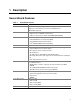
1 Description Server Board Features Table 1.
Back Panel Connectors The back panel connectors are color-coded in compliance with PC 99 recommendations. A C F B D E G H I OM14342 A. B. C. D. E. F. G. H. I. PS/2 mouse PS/2 keyboard Parallel port Serial port A Video port NIC 1 USB port 1 USB port 2 NIC 2 Figure 1.
Front Panel Connectors Figure 2 shows the location of the front panel connectors. B A A. B. OM14351 Front Panel Header HDD LED Figure 2.
Server Board Connector and Component Locations A D B C E F G H CC BB I AA J K Z L Y M X W V U S R Q P O T A. B. C. D. E. F. G. H. I. J. K. L. M. N. O.
Processors The S845WD1-E board supports a single Intel Pentium 4 processor with a µPGA478 socket. Processors are not included with the server board and must be purchased separately. Table 2. Supported Processors Type Designation System Bus L2 Cache Size Pentium 4 processor 1.6, 1.8, 2.0, 2.26, and 2.4 GHz 400 / 533 MHz 512 KB Pentium 4 processor 1.8, 1.9, and 2.0 GHz 400 MHz 256 KB Intel Celeron processor 1.7, 1.8, and 1.
DIMM and memory configurations must adhere to the following: • 2.5 V (only) 184-pin DDR SDRAM DIMMs with gold-plated contacts • Unbuffered single-sided or double-sided DIMMs. • Maximum total system memory: 2 GB; Minimum total system memory: 64 MB • 200/266 MHz DDR SDRAM DIMMs only • Serial Presence Detect (SPD) • Suspend to RAM • Non-ECC and ECC DIMMs • Only DIMMs tested and qualified by Intel or a designated memory test vendor will be supported on the S845WD1-E server board.
Intel 82801BA I/O Controller Hub (ICH2) The Intel 82801BA ICH2 has these features: • 33 MHz Peripheral Component Interface (PCI) Local Bus slots supporting PCI specification, Rev 2.2. • Support for the Low Pin Count (LPC) interface. • Integrated IDE controller (supports Ultra ATA-66/100 mode and Ultra DMA 33 mode). • Integrated LAN media access controller.
Serial Ports The S845WD1-E server board has one serial port connector and one serial port header. The serial port A connector is located on the back panel. The serial port B header is located near the main power connector. The serial ports’ NS16C550-compatible UART supports data transfers at speeds up to 115.2 kb/s with BIOS support. Parallel Port The 25-pin D-Sub parallel port connector is located on the back panel.
Hardware Management ASIC The Hardware Management ASIC provides low-cost instrumentation capabilities. The features of the component include: • Internal ambient temperature sensing • Remote thermal diode sensing for direct monitoring of processor temperature • Power supply monitoring (+5 V, +3.3 V, +1.5 V, 3.3 VSB, and Vccp) to detect levels above or below acceptable values • SMBus interface Fan Monitoring The Hardware Management ASIC provides four fan tachometer inputs.
Legacy USB Support Legacy USB support enables USB devices such as keyboard, mice, and hubs to be used even when the operating system’s USB drivers are not yet available. Legacy USB support is used to access the BIOS Setup program, and to install an operating system that supports USB. By default, Legacy USB support is set to Enabled. The S845WD1-E server board has four USB 1.1 ports; one USB peripheral can be connected to each port.
IDE Support IDE Interfaces The ICH2’s IDE controller has two independent bus-mastering IDE interfaces that can be independently enabled. The IDE interfaces support the following modes: • Programmed I/O (PIO): processor controls data transfer. • 8237-style DMA: DMA offloads the processor, supporting transfer rates of up to 16 MB/sec. • Ultra DMA: DMA protocol on IDE bus supporting host and target throttling and transfer rates of up to 33 MB/sec.
BIOS The S845WD1-E server board uses an Intel/AMI BIOS that is stored in the Firmware Hub (FWH) and can be updated using a disk-based program. The FWH contains the BIOS Setup program, POST, the PCI auto-configuration utility, and Plug and Play support. The S845WD1-E server board supports system BIOS shadowing, allowing the BIOS to execute from 64-bit onboard write-protected system memory. The BIOS displays a message during POST identifying the type of BIOS and a revision code.
BIOS Updates The BIOS can be updated using either of the following utilities, which are available on the Intel World Wide Web site: • Intel® Express BIOS update utility, which enables automated updating while in the Windows environment. Using this utility, the BIOS can be updated from a file on a hard disk, a 1.44 MB diskette, or a CD-ROM, or from the file location on the Web. • Intel® Flash Memory Update Utility, which requires creation of a boot diskette and manual rebooting of the system.
Recovering BIOS Data Some types of failure can destroy the BIOS. For example, the data can be lost if a power outage occurs while the BIOS is being updated in flash memory. The BIOS can be recovered from a diskette using the BIOS recovery mode. When recovering the BIOS, be aware of the following: • Because of the small amount of code available in the non-erasable boot block area, there is no video support.
Boot Options In the BIOS Setup program, the user can choose to boot from a diskette drive, hard drives, CD-ROM, or the network. The default setting is for the diskette drive to be the first boot device, the hard drive second, and the ATAPI CD-ROM third. The fourth device is disabled. CD-ROM and Network Boot Booting from CD-ROM is supported in compliance to the El Torito bootable CD-ROM format specification. Under the Boot menu in the BIOS Setup program, ATAPI CD-ROM is listed as a boot device.
Fast Booting Systems with Intel® Rapid BIOS Boot These factors affect system boot speed: • Selecting and configuring peripherals properly • Using an optimized BIOS, such as the Intel Rapid BIOS Intel Rapid BIOS Boot Using the following BIOS Setup program settings reduces the POST execution time. In the Boot Menu: • Set the hard disk drive as the first boot device. As a result, the POST does not first seek a diskette drive, which saves about one second from the POST execution time.
BIOS Security Passwords The BIOS includes security features that restrict whether the BIOS Setup program can be accessed and who can boot the server. A supervisor password and a user password can be set for the Setup menu and for booting the server, with the following restrictions: • The supervisor password gives unrestricted access to view and change all Setup options. If only the supervisor password is set, pressing at the password prompt of Setup gives the user restricted access to Setup.
System Management BIOS (SMBIOS) SMBIOS is a Server Management Interface (DMI) compliant method for managing computers in a managed network. The main component of SMBIOS is the Management Information Format (MIF) database, which contains information about the computing system and its components. Using SMBIOS, a system administrator can obtain the system types, capabilities, operational status, and installation dates for system components.
Power Management Features Power management is implemented at several levels, including: • Software support through Advanced Configuration and Power Interface (ACPI) • Hardware support: Power connector Fan connectors LAN wake capabilities Instantly Available PC technology Resume on Ring Wake from USB Wake from PS/2 devices Power Management Event (PME#) wake-up support Wake on LAN Technology Network adapters that are PCI 2.
Resume on Ring The operation of Resume on Ring can be summarized as follows: • Resumes operation from the ACPI S1. • Requires only one call to access the server. • Detects incoming call similarly for external and internal modems; does not use the Wake on Ring connector. • Requires modem interrupt be unmasked for correct operation. ACPI ACPI gives the operating system direct control over the power management and Plug and Play functions of a computer.
Table 5 lists the system states based on how long the power switch is pressed, depending on how ACPI is configured with an ACPI-aware operating system. Table 5.
Table 6. Power States and Targeted System Power (continued) Processor States Sleeping States G2/S5 S5 – Soft off. Context not saved. Cold boot is required. No power D3 – no power except for wake-up logic. Power < 5 W G3 – mechanical off No power to the system. No power D3 – no power for wake-up logic, except when provided by battery or external source. No power to the system. Service can be performed safely. AC power is disconnected from the computer.
Hardware Support The S845WD1-E server board provides several power management hardware features, including: • Power connector • Fan connectors • LAN wake capabilities • Instantly Available PC technology • Resume on Ring • Wake from USB • Wake from PS/2 keyboard • PME# wake-up support LAN wake capabilities and Instantly Available PC technology require power from the +5 V standby line. The sections discussing these features describe the incremental standby power requirements for each.
Power Connector When used with an ATX12V or EPS-12 V compliant power supply that supports remote power on/off, the S845WD1-E server board can turn off the system power through software control. When the system BIOS receives the correct command from the operating system, the BIOS turns off power to the computer.
Instantly Available PC Technology CAUTION For Instantly Available PC technology, the +5 V standby line for the power supply must be capable of providing adequate +5 V standby current. Failure to provide adequate standby current when implementing Instantly Available PC technology can damage the power supply. The S845WD1-E server board supports the PCI Bus Power Management Interface Specification.
Resume on Ring The operation of Resume on Ring can be summarized as follows: • Resumes operation from ACPI S1 state • Requires only one call to access the computer • Detects incoming call similarly for external and internal modems • Requires modem interrupt be unmasked for correct operation Wake from USB USB bus activity wakes the computer from an ACPI S1 state. ✏ NOTE Wake from USB requires the use of a USB peripheral that supports Wake from USB.
PCI I/O Subsystem The primary I/O bus for the S845WD1-E server board is PCI, with one independent PCI bus. The PCI bus complies with the PCI Local Bus Specification, Rev 2.2. The PCI bus is directed through the Intel 82801BA I/O Controller Hub (ICH2). The table below lists the characteristics of the PCI bus. Table 9.
Table 10. PCI Bus Configuration IDs (continued) IDSEL Value 30 Device ATA-100 controller Promise Technology PDC20267 31 ATI Rage XL Video Controller PCI Arbitration The PCI bus supports six PCI masters (ATI Rage XL, two Intel 82550s, Promise ATA-100 Controller, PCI connector 1 and an arbiter (PCI connector 2 and PCI connector 3). All PCI masters must arbitrate for PCI access, using resources supplied by the ICH2.
Video Controller The S845WD1-E server board provides an ATI Rage XL PCI graphics accelerator, along with 2 MB of video SDRAM and support circuitry for an embedded SVGA video subsystem. The ATI Rage XL chip contains a SVGA video controller, clock generator, 2D and 3D engine, and RAMDAC in a 272-pin PBGA. One 2Mx32 SDRAM chip provides 2 MB of video memory.
Video Memory Interface The memory controller subsystem of the Rage XL arbitrates requests from direct memory interface, the VGA graphics controller, the drawing coprocessor, the display controller, the video scalar, and hardware cursor. Requests are serviced in a manner that ensures display integrity and maximum CPU/coprocessor drawing performance. The S845WD1-E supports a 2 MB (512Kx32bitx4 Banks) SDRAM device for video memory.
Hardware Monitoring The S845WD1-E server board has an integrated Hardware Management ASIC that is responsible for hardware monitoring. Together, the Hardware Management ASIC and the Intel® LANDesk® Client Manager (LDCM) 6.3 software provide basic server hardware monitoring which alerts a system administrator if a hardware problem occurs on an Intel Server Board S845WD1-E based system. The Intel LDCM software is for use with Windows 2000 Server and Windows 2000 Advanced Server operating systems.
Intel Server Board S845WD1-E Product Guide
2 Server Board Installation and Upgrading Tools and Supplies Needed • • • • Phillips† (cross head) screwdriver (#1 bit and #2 bit) Jumper removal tool or needle nosed pliers Pen or pencil Antistatic wrist strap and conductive foam pad (recommended) Before You Begin Emissions Disclaimer To ensure EMC compliance with your local regional rules and regulations, the final configuration of your end system product may require additional EMC compliance testing.
Electrostatic discharge (ESD) & ESD protection: ESD can damage disk drives, boards, and other parts. We recommend that you perform all procedures in this chapter only at an ESD workstation. If one is not available, provide some ESD protection by wearing an antistatic wrist strap attached to chassis groundany unpainted metal surfaceon your server when handling parts. ESD and handling boards: Always handle boards carefully. They can be extremely sensitive to ESD. Hold boards only by their edges.
Memory The SE845WD1-E server board contains two 184-pin DIMM sockets and supports up to two DDR SDRAM DIMMs. The minimum supported memory configuration is 64 MB and the maximum configurable memory size is a 2 GB stacked un-buffered DDR200/266 ECC DIMM. ✏ NOTE Only low profile DIMMs can be supported in a 1U server chassis. Check the Intel Customer Support website for the latest tested memory list: http://support.intel.
1 2 OM14343 Figure 5. DIMM Socket Locations 4. Make sure the clips at either end of the DIMM socket(s) are pushed outward to the open position. 5. Holding the DIMM by the edges, remove it from its anti-static package. 6. Position the DIMM above the socket. Align the two small notches in the bottom edge of the DIMM with the keys in the socket (see inset in Figure 5). 7. Insert the bottom edge of the DIMM into the socket. 8.
Installing the I/O Shield CAUTION Systems based on the S845WD1-E server board need the I/O shield properly installed to pass emissions (EMI) certification testing and to meet Class B emissions compliance levels. Without the I/O shield, or with an improperly installed I/O shield, the server system will not meet Class B regulatory compliance requirements. The boxed server board comes with an I/O shield for a general purpose chassis.
Installing the Server Board Refer to your chassis manual for instructions on installing the server board. Eight screws secure the server board to the chassis. Figure 7 shows the locations of the mounting screw holes. ✏ NOTES You will need a Phillips (#2 bit) screwdriver. Refer to Page 93 for regulatory requirements and installation instructions and precautions. WARNING Only qualified technical personnel should attempt this procedure.
Installing a Processor To install a processor, follow these instructions: 1. Observe the safety and ESD precautions at the beginning of this chapter. 2. Locate the processor socket and raise the socket handle completely (see Figure 8, B). 3. Aligning the pins of the processor with the socket, insert the processor into the socket (see Figure 8, A and C). 4. Close the handle completely (see Figure 8, D). D B C A OM14263 Figure 8. Installing the Processor in the Processor Socket 5.
7. Attach the fan heat sink clips to the processor socket. a. Align the heat sink and clip assembly with the retention mechanism and place it on the processor. The heat sink is symmetrical. b. With the clip levers in the up position, use a flat head screw drive to push down on all four clip frame corners to secure to the retention mechanism hooks (see Figure 10). c. Close the clip levers completely. OM14470 Figure 10. Attaching the Fan Heat Sink Clips to the Processor Socket 8.
Removing the Processor To remove the processor, follow these instructions: 1. Observe the safety and ESD precautions at the beginning of this chapter. 2. Disconnect the processor fan cable. 3. Detach the fan heat sink clips. 4. Remove the heat sink. 5. Raise the socket handle completely. 6. Remove the processor.
Replacing the Battery When your server is turned off, a lithium battery maintains the time-of-day clock and the keeps the values in CMOS RAM. The location of the server board battery is shown in Figure 12 on page 52. The battery should last about seven years whereupon it begins to lose voltage. When the voltage drops below a certain level, the BIOS Setup program settings stored in CMOS RAM (for example, the date and time) might not be accurate. Replace the battery with an equivalent one.
VARO Räjähdysvaara, jos pariston tyyppi on väärä. Paristot on kierrätettävä, jos se on mahdollista. Käytetyt paristot on hävitettävä paikallisten ympäristömääräysten mukaisesti. (Finnish) VORSICHT Bei falschem Einsetzen einer neuen Batterie besteht Explosionsgefahr. Die Batterie darf nur durch denselben oder einen entsprechenden, vom Hersteller empfohlenen Batterietyp ersetzt werden. Entsorgen Sie verbrauchte Batterien den Anweisungen des Herstellers entsprechend.
To replace the battery, follow these steps: 1. Observe the safety and ESD precautions at the beginning of this chapter. 2. Turn off all peripheral devices connected to the server. Disconnect the server’s power cord from the AC power source (wall outlet or power adapter). 3. Remove the server cover. 4. Locate the battery on the board (see Figure 12). 5. With your fingertip, gently pull back the tab away from the battery. Pull out the battery. Note the orientation of the “+” and “-” on the battery. 6.
Connecting the IDE Cable The Intel® boxed server board package includes a 40-contact, 80-conductor IDE cable. It is capable of connecting two drives to the server board. The cable supports Ultra ATA/66 and Ultra ATA/100 transfer protocols and is backward compatible with drives using slower IDE transfer protocols. For the cable to function correctly: • Attach the cable end with the single connector (A), which is black and labeled PRI IDE, to the server board as shown in Figure 13.
Setting the BIOS Configuration Jumper CAUTION Always turn off the power and unplug the power cord from the server before changing the jumper. Moving the jumper with the power on may result in unreliable server operation. J6H1 OM14346 Figure 14. BIOS Configuration Jumper Block Location This three-pin jumper block, shown in Figure 14, enables all server board configurations to be done in BIOS Setup. Table 12 shows the jumper settings for the Setup program modes. Table 12.
3 Configuration Software and Utilities This chapter tells you how to update the BIOS by either using the Intel® Express BIOS Update utility or the Intel® Flash Memory Update Utility, and recovering the BIOS if an update fails. Updating the BIOS with the Intel Express BIOS Update Utility With the Intel Express BIOS Update utility you can update the system BIOS while in the Windows environment.
Obtaining the BIOS Update File You can update to a new version of the BIOS by using the BIOS update file. The BIOS update file is a compressed self-extracting archive that contains all the files you need to update the BIOS. The BIOS update file contains: • New BIOS files • BIOS recovery files • Intel Flash Memory Update Utility You can obtain the BIOS update file through your server supplier or from the Intel World Wide Web site: http://support.intel.
Creating a Bootable Diskette ✏ NOTE If your drive A is an LS-120 diskette drive, you must use a 1.44-MB diskette as the bootable BIOS update diskette. The server is unable to recover a BIOS from an LS-120 diskette. To create a bootable diskette using a DOS system: • Place an unformatted diskette in the diskette drive and format the diskette using the /s option. Example: format a: /s • Alternatively, place a formatted diskette in the diskette drive and use the sys command.
Updating the BIOS CAUTION 1. 2. 3. 4. 5. The AUTOEXEC.BAT file provided with the update files updates the BIOS in two parts: first updating the boot block and displaying the Operation completed successfully message and second, updating the BIOS core. You will be asked to reboot the system when the update process is complete. Do not interrupt the process or the system may not be capable of rebooting. Boot the server with the BIOS upgrade diskette in drive A. During system boot, the AUTOEXEC.
Recovering the BIOS It is unlikely that anything will interrupt the BIOS update, however, if an interruption occurs, the BIOS could be damaged. The following steps explain how to recover the BIOS if an update fails. The following procedure uses recovery mode for the Setup program. See page 54 for more information on Setup modes. ✏ NOTE Because of the small amount of code available in the boot block area, there is no video support. You will not see anything on the screen during this procedure.
Using the Setup Program You can use the BIOS Setup program to change the configuration information and boot sequence for the server. This chapter tells you how to access the BIOS Setup program and lists Setup features, options, and default settings. ✏ NOTE For reference purposes, you should write down the current Setup settings. When you make changes to the settings, update this record.
Table 14 shows the function keys available for menu screens. Table 14.
Extended Configuration Submenu To access this submenu, select Maintenance on the menu bar, then Extended Configuration. Maintenance Main Advanced Security Power Boot Exit Extended Configuration The submenu represented by Table 16 is for setting video memory cache mode. This submenu becomes available when User Defined is selected under Extended Configuration. Table 16.
Main Menu To access this menu, select Main on the menu bar at the top of the screen. Maintenance Main Advanced Security Power Boot Exit Table 17 describes the Main Menu. This menu reports processor and memory information and is for configuring the system date and system time. Table 17. Main Menu Feature ✏ Options Description BIOS Version No options Displays the version of the BIOS. Processor Type No options Displays processor type. Processor Speed No options Displays processor speed.
Advanced Menu To access this menu, select Advanced on the menu bar at the top of the screen. Maintenance Main Advanced Security Power Boot Exit PCI Configuration Boot Configuration Peripheral Configuration IDE Configuration Diskette Configuration Event Log Configuration Table 18 describes the Advanced Menu. This menu is used for setting advanced features that are available through the chipset. Table 18.
PCI Configuration Submenu To access this submenu, select Advanced on the menu bar, then PCI Configuration. Maintenance Main Advanced Security Power Boot Exit PCI Configuration Boot Configuration Peripheral Configuration IDE Configuration Diskette Configuration Event Log Configuration The submenu represented by Table 19 is for configuring the IRQ priority of PCI slots individually. Table 19.
Boot Configuration Submenu To access this submenu, select Advanced on the menu bar, then Boot Configuration. Maintenance Advanced Main Security Power Boot Exit PCI Configuration Boot Configuration Peripheral Configuration IDE Configuration Diskette Configuration Event Log Configuration The submenu represented by Table 20 is for setting Plug and Play (PnP) options, resetting configuration data, and the power-on state of the Numlock key. Table 20.
Peripheral Configuration Submenu To access this submenu, select Advanced on the menu bar, then Peripheral Configuration. Maintenance Main Advanced Security Power Boot Exit PCI Configuration Boot Configuration Peripheral Configuration IDE Configuration Diskette Configuration Event Log Configuration The submenu represented in Table 21 is used for configuring server peripherals. Table 21.
Table 21. Peripheral Configuration Submenu (continued) Feature Options Description Mode • Normal (default) Specifies the mode for serial port B. • IrDA SIR-A • ASK-IR Parallel Port • Disabled Configures the parallel port. • Enabled Auto assigns LPT1 the address 378h and the interrupt IRQ7. • Auto (default) An * (asterisk) displayed next to an address indicates a conflict with another device. Mode • Output Only • Bi-directional (default) Selects the mode for the parallel port.
IDE Configuration Submenu To access this submenu, select Advanced on the menu bar, then IDE Configuration. Maintenance Main Advanced Security Power Boot Exit PCI Configuration Boot Configuration Peripheral Configuration IDE Configuration Diskette Configuration Event Log Configuration The menu represented in Table 22 is used to configure IDE device options. Table 22. IDE Configuration Submenu Feature Options Description IDE Controller • Disabled Specifies the integrated IDE controller.
Primary/Secondary IDE Master/Slave Submenus To access these submenus, select Advanced on the menu bar, then IDE Configuration, and then the master or slave to be configured.
Table 23. Primary/Secondary IDE Master/Slave Submenus (continued) Feature Options Description PIO Mode (Note) • Auto (default) Specifies the PIO mode. (This feature is present only when Type is not set to Auto.) • Mode 0 • Mode 1 • Mode 2 • Mode 3 • Mode 4 Ultra DMA • Disabled (default) (This feature is present only when Type is not set to Auto.) • Mode 0 Specifies the Ultra DMA mode for the drive.
Table 24. Diskette Configuration Submenu (continued) Feature Options Description Floppy B • Not Installed (default) Specifies the capacity and physical size of diskette drive B. Diskette Write-Protect • 360 KB 5¼" • 1.2 MB 5¼" • 720 KB 3½" • 1.44/1.25 MB 3½" • 2.88 MB 3½" • Disabled (default) Disables or enables write-protect for the diskette drive. • Enabled Event Log Configuration Submenu To access this menu, select Advanced on the menu bar, then Event Log Configuration.
Video Configuration Submenu To access this menu, select Advanced on the menu bar, then Event Log Configuration. Maintenance Main Advanced Security Power Boot Exit PCI Configuration Boot Configuration Peripheral Configuration IDE Configuration Diskette Configuration Event Log Configuration Video Configuration The submenu represented by Table 26 is used to configure the video features. Table 26.
Security Menu To access this menu, select Security from the menu bar at the top of the screen. Maintenance Main Advanced Security Power Boot Exit The menu represented by Table 27 is for setting passwords and security features. Table 27. Security Menu If no password entered previously: Feature Options Description Supervisor Password Is No options Reports if there is a supervisor password set. User Password Is No options Reports if there is a user password set.
Power Menu To access this menu, select Power from the menu bar at the top of the screen. Maintenance Main Advanced Security Power Boot Exit ACPI The menu represented in Table 28 is for setting the power management features. Table 28. Power Menu Feature Options Description ACPI No Options When selected, displays the ACPI submenu. After Power Failure • Stays Off Specifies the mode of operation if an AC power loss occurs. • Last State (default) Power On restores power to the server.
Boot Menu To access this menu, select Boot from the menu bar at the top of the screen. Maintenance Main Advanced Security Power Boot Exit Boot Device Priority Hard Disk Drives Removable Devices ATAPI CD-ROM Drives The menu represented in Table 30 is used to set the boot features and the boot sequence. Table 30. Boot Menu Feature Options Description Quiet Boot • Disabled Disabled displays normal POST messages. • Enabled (default) Enabled displays OEM graphic instead of POST messages.
Boot Device Priority Submenu To access this menu, select Boot on the menu bar, then Boot Devices Priority. Maintenance Main Advanced Security Power Boot Exit Boot Device Priority Hard Disk Drives Removable Devices ATAPI CDROM Drives The submenu represented in Table 31 is for setting boot devices priority. Table 31. Boot Device Priority Submenu Feature Options Description st • Removable Dev. nd 2 Boot Device • Hard Drive Specifies the boot sequence from the available types of boot devices.
Hard Disk Drives Submenu To access this menu, select Boot on the menu bar, then Hard Disk Drives. Maintenance Main Advanced Security Power Boot Exit Boot Device Priority Hard Disk Drives Removable Devices ATAPI CDROM Drives The submenu represented in Table 32 is for setting hard disk drive priority. Table 32. Hard Disk Drives Submenu Feature st 1 Hard Disk Drive (Note) Options Description Dependent on installed hard drives Specifies the boot sequence from the available hard disk drives.
ATAPI CDROM Drives Submenu To access this menu, select Boot on the menu bar, then ATAPI CDROM Drives. Maintenance Main Advanced Security Power Boot Exit Boot Device Priority Hard Disk Drives Removable Devices ATAPI CDROM Drives The submenu represented in Table 34 is for setting ATAPI CDROM drive priority. Table 34.
Intel Server Board S845WD1-E Product Guide
4 Solving BIOS Problems The board reports POST errors in two ways: • By sounding a beep code • By displaying an error message on the monitor BIOS Beep Codes The BIOS beep codes are listed in Table 36. The BIOS also issues a beep code (one long tone followed by two short tones) during POST if the video configuration fails, or if an external ROM module does not properly checksum to zero. Table 36.
BIOS Error Messages When a recoverable error occurs during the POST, the BIOS displays an error message describing the problem (see Table 37). Table 37. BIOS Error Messages Error Message Explanation GA20 Error An error occurred with Gate A20 when switching to protected mode during the memory test. Pri Master HDD Error Pri Slave HDD Error Sec Master HDD Error Sec Slave HDD Error Could not read sector from corresponding drive.
Table 37. BIOS Error Messages (continued) Error Message Explanation Memory Size Decreased Memory size has decreased since the last boot. If no memory was removed, then memory may be bad. Memory Size Increased Memory size has increased since the last boot. If no memory was added, there may be a problem with the system. Memory Size Changed Memory size has changed since the last boot. If no memory was added or removed, then memory may be bad.
Intel Server Board S845WD1-E Product Guide
5 Getting Help World Wide Web http://support.intel.com/support/motherboards/server/S845WD1-E Telephone Talk to a Customer Support Technician.* All calls are billed US $25.00 per incident, levied in local currency at the applicable credit card exchange rate plus applicable taxes. (Intel reserves the right to change the pricing for telephone support at any time without notice). In U.S.
Intel Server Board S845WD1-E Product Guide
6 Technical Reference Server Board Connectors CAUTION Many of the baseboard and front panel connectors provide operating voltage (+5 V DC and +12 V DC, for example) to devices inside the server chassis, such as fans and internal peripherals. These connectors are not overcurrent protected. Do not use these connectors for powering devices external to the server chassis.
Add-In Board and Peripheral Interface Connectors Figure 16 shows the add-in board and peripheral interface connectors. A B C 40 2 1 2 1 2 1 F E 39 40 39 34 33 D OM14349 A. B. C. D. E. F. PCI slot 3 PCI slot 2 PCI slot 1 Diskette drive Primary IDE Secondary IDE Figure 16.
Server Board Resources Memory Map Table 38.
I/O Map Table 40.
Table 40.
Table 41.
7 Regulatory and Integration Information Product Regulatory Compliance Product Safety Compliance The S845WD1-E complies with the following safety requirements: • UL 1950 - CSA 950 (US/Canada) • EN 60 950 (European Union) • IEC60 950 (International) • CE – Low Voltage Directive (73/23/EEC) (European Union) • EMKO-TSE (74-SEC) 207/94 (Nordics) • GOST R 50377-92 (Russia) Product EMC Compliance The S845WD1-E has been has been tested and verified to comply with the following electromagnetic compatibility (EMC)
Product Regulatory Compliance Markings This product is marked with the following Product Certification Markings: Table 42. Product Certification Markings UL Recognition Mark CE Mark Russian GOST Mark Australian C-Tick Mark BSMI DOC Marking BSMI EMC Warning RRL MIC Mark Electromagnetic Compatibility Notices FCC (USA) This device complies with Part 15 of the FCC Rules.
This equipment has been tested and found to comply with the limits for a Class A digital device, pursuant to Part 15 of the FCC Rules. These limits are designed to provide reasonable protection against harmful interference in a residential installation. This equipment generates, uses, and can radiate radio frequency energy and, if not installed and used in accordance with the instructions, may cause harmful interference to radio communications.
Korean RRL Compliance This product has been tested and complies with MIC Notices No. 1997-41 and 1997-42. The product has been marked with the MIC logo to illustrate compliance. The English translation for the above is as follows: 1. Type of Equipment (Model Name): S845WD1-E 2. Certification No.: Contact Intel Representative 3. Name of Certification Recipient: Intel 4. Date of Manufacturer: Marked on Product 5.
Installation Requirements CAUTION Follow these guidelines to meet safety and regulatory requirements when installing this board assembly. Read and adhere to all of these instructions and the instructions supplied with the chassis and associated modules. If the instructions for the chassis are inconsistent with these instructions or the instructions for associated modules, contact the supplier’s technical support to find out how you can ensure that your computer meets safety and regulatory requirements.
Intel Server Board S845WD1-E Product Guide