
Service Guide


50 Intel
®
Server System SR2612UR Service Guide
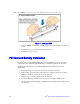
Figure 43. Routing the Cables Through the Fan Assembly
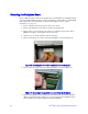
12. If there is an external battery associated with the PCI card, it must be mounted with
the supplied mounting screws in the location indicated in the following figure
Figure 44. Mounting an External Battery
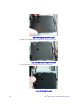
13. Reinstall the top cover and tighten the captive screw.
A - POWER SUPPLY
B - POWER DIST BOARD
C - PCI RISER ASSY
D - SERVER BOARD
E - BACKPLANE PCB
F - HARD DRIVE ASSY
G - SYSTEM AIR DUCT
H - FAN MODULE
I - 2.5” SYSTEM DRIVES
J - RAID CARD BATTERY
K - CD/DVD DRIVE
I
F
A
C
D
E
G
H
B
J
K
OPTIONAL HARDWARE