
Service Guide


20 Intel
®
Server System SR2612UR Service Guide
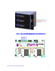
Figure 13. Server Board Connector and Component Locations
A. 280-pin Intel
®
Adaptive Slot B. POST Code Diagnostic LEDs C. Intel
®
RMM3 Header
D. Processor 1 Socket E. Back Panel I/O Ports F. System Identification LED
G. System Status LED H. Memory 1 Fan Header I. CPU 1 Fan Header
J. Processor 1 DIMM slots K. Processor 2 DIMM slots L. Processor 2 Socket
M. CPU 2 Fan Header N. Memory 2 Fan Header O. Bridge Board Connector (Intel
®
Server Chassis)
P. Front Panel Connector Q. Fan Board Connector R. 2x4 Power Connector
S. Main Power Connector T. Power Supply SMBus
Connector
U. System 2 Fan Header
V. USB Header W. Low-profile USB Solid State
Drive Header
X. System 1 Fan Header
Y. LCP IPMB Header Z. SATA RAID 5 Key Header AA. SGPIO Header
BB. SATA Connectors CC. I/O Module Mezzanine
Connector 2
DD. I/O Module Mezzanine
Connector 1
EE. Serial Port B Header