
Technical Product Specification


6BStandard Control Panel Intel®
Server System SR2600UR TPS
72 Intel order number E45274-011 Revision 1.8
7.2.4 System Identification LED
The blue system identification LED is used to help identify a system for servicing. This is
especially useful when the system is installed in a high-density rack or cabinet that is populated
with several similar systems.
The blue system ID LED can be illuminated using one of the following mechanisms:
By pressing the system ID button on the system control panel, the ID LED displays a
solid blue color until the button is pressed again.
By issuing the appropriate hex IPMI system identify value, the ID LED either blinks blue
for 15 seconds and turns off or blinks indefinitely until the appropriate hex IPMI system
identify value is issued to turn it off.
7.3 Control Panel Connectors
The control panel has two external I/O connectors:
One USB port
One VGA video port
The following tables provide the pin-outs for each connector.
Table 50. External USB Connectors (J1B1)
Pin #
Description
1
PWR_FP_USB2
2
USB_DN2_FP_R
3
USB_DP2_FP_R
4
GND
5
GND
6
GND
7
GND
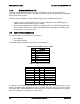
Table 51. Video Connector (J1A1)
Description
Pin #
Pin #
Description
VGA_RED 1 9 GND
VGA_GREEN 2 10 GND
VGA_BLUE 3 11 Unused
Unused 4 12 VGA_DDCDAT
GND 5 13 VGA_HSYNC_L
GND 6 14 VGA_VSYNC_L
VGA_INUSE_L 7 15 VGA_DDCCLK
GND 8 16 GND
17 GND
If a monitor is connected to the control panel video connector, the rear video port on the server
board is disabled and the control panel video is enabled. The video source is the same for both
connectors and is switched between the two, with the rear video having priority over the control
panel. This provides easy front access to the server.