
Technical Product Specification


Intel®
Server System SR2600UR TPS Peripheral and Hard Drive Subsystem
Revision 1.8 Intel order number E45274-011
55
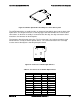
Figure 28. Slimline Optical Drive Assembly for 3.5-inch drive System
The SATA Optical drive assembly includes an interposer board which plugs into the back of the
optical drive. The interposer board is a card-edge type card that eliminates the need for cable
connections. As the drive assembly is inserted into the drive bay, the edge connector is blind
mated to a slot connector on the backplane.
The interposer board has two connectors. The first connector is the industry standard 13-pin
SATA interface used by all slimline optical devices. The second connector is the card edge
used to connect directly to the hot-swap backplane board.
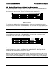
Figure 29. Connector to Slimline Optical Device
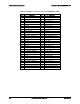
Table 43. J1L1 Connector to Slimline Optical Device
Pin #
Signal Name
Pin #
Signal Name
A1
P5V
B1
GND
A2
P5V
B2
SATA_TXP
A3
P5V
B3
SATA_TXN
A4
P5V
B4
GND
A5
P5V
B5
GND
A6
P5V
B6
SATA_RXN
A7
P5V
B7
SATA_RXP
A8
P5V
B8
GND
A9
P5V
B9
GND
A10
P5V
B10
GND
A11
P5V
B11
GND