
Technical Product Specification


Connector/Header Locations and Pin-outs Intel® Server Board S5520UR and S5520URT TPS
Intel order number E44031-012 Revision 1.9
112
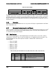
Table 68. Power Budget
Power Rails
3.3V
5V
12V
3.3VAUX
N12V
Max Current Per Rail (A)
17.7 5 7.3 1 1
It’s important to note that the above “Board-Level” power budget does not take into account the
limitations placed at the “System-Level” power budget.
The above current numbers should only
be understood as the maximum current limit that the design can handle. The riser and server
board in the system must comply with any System-Level limitations that are typically set due to
thermal concerns.
6.7.6 Decoupling
Decoupling caps must be added on the riser as per the PCI Express Specification for all Power
Rails used on the riser.
6.7.7 Mechanical Considerations for Intel
®
Chassis
There are various mechanical considerations that must be followed when designing for an Intel
®
Server Chassis.
Use the mechanical control drawings of the 1U and 2U Intel
®
-designed risers
as reference for any custom designs.
6.8 Fan Headers
The server board provides six SSI-compliant 4-pin fan headers to be used as CPU, and I/O
cooling fans in non-Intel
®
chassis. 3-pin and 4-pin fans are supported on all fan headers. The
pin configuration for each of the 4-pin fan headers is identical and is defined in the
following table.
CPU1 fan (J9A4)
CPU2 fan (J9K2)
MEM1 fan (J8K1)
MEM2 fan (J9A3)
SYS1 fan (J3J2)
SYS2 fan (J3J1)
Table 69. SSI 4-pin Fan Header Pin-out (J9A4, J9K2, J8K1, J9A3, J3J2, and J3J1)
Pin
Signal Name
Type
Description
1
Ground
GND
Ground is the power supply ground
2
12 V
Power
Power supply 12 V
3
Fan Tach
In
FAN_TACH signal is connected to the Integrated
BMC to monitor the fan speed
4
Fan PWM
Out
FAN_PWM signal to control fan speed