
Technical Product Specification


Connector/Header Locations and Pin-outs Intel® Server Board S5520UR and S5520URT TPS
Intel order number E44031-012 Revision 1.9
108
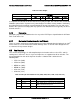
Pin
Side
B
PCI Express* Signal
PCI Express* Signal
Pin
Side
A
Pin
Side
B
PCI Express* Signal
PCI Express* Signal
Pin
Side
A
67
GND
RN[7] { PE5_Rp [0] }
67
138
REFCLK+ [7]
REFCLK- [6]
138
68
TP[6] { PE5_Tn [1] }
GND
68
139
REFCLK- [7]
GND
139
69
TN[6] { PE5_Tp [1] }
GND
69
140
Riser Type [3]
Riser Type [2]
140
Table 63. Pin Type Description
Pin Types
Description
3.3 V
3.3 V Power Rail
12 V
12 V Power Rail
N12 V
Negative 12 V Power Rail
3.3VAUX
3.3 V AUX Rail
5 V
5 V Power Rail for PCI-X
PE
PCI Express* Gen2 Signals
SMBus
SMBus Signals have been removed; No SW support
MISC
WAKE#, PERST#, CH INTR, PME#
JTAG
These have been removed
CLKS
Clocks
Riser Type
Riser Type Signals
RSVD Reserved Pins
6.7.1 PCI Express* Port Bifurcation
The IOH supports various combinations of link sizes ranging from x2 to x16 through bifurcation
of PCI Express* ports. However, the ports that can be combined to form larger links are limited.
You cannot combine any ports to form a larger link. The following table details how the ports
can be combined.