
Technical Product Specification


Intel® Local Control Panel Intel® Server System SR2625UR TPS
Intel order number E46130-010 Revision 1.8
80
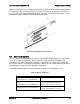
Color
State
Criticality
Description
recoverable
Including, but not limited to:
DIMM failure when there is one DIMM present, no good
memory present.
Run-time memory uncorrectable error in non-redundant mode
IERR signal asserted.
Processor 1 missing.
Temperature (e.g. CPU ThermTrip, memory TempHi, critical
threshold crossed).
No power good – power fault.
Processor configuration error (e.g. processor stepping mismatch).
8.1.3 Drive Activity LED
The drive activity LED on the front panel indicates drive activity from the on-board hard disk
controllers. The Intel
®
Server Board S5520UR also provides a header giving access to this LED
for add-in controllers.
8.1.4 System Identification LED
The blue system identification LED is used to help identify a system for servicing. This is
especially useful when the system is installed in a high-density rack or cabinet that is populated
with several similar systems.
The blue system ID LED can be illuminated using one of the following mechanisms:
By pressing the system ID button on the system control panel, the ID LED displays a
solid blue color until the button is pressed again.
By issuing the appropriate hex IPMI system identify value, the ID LED either blinks blue
for 15 seconds and turns off or blinks indefinitely until the appropriate hex IPMI system
identify value is issued to turn it off.
8.2 Intel
®
Local Control Panel Interconnects
The Intel
®
Local Control Panel module is cabled to matching connectors on the backplane.
When the pre-assembled control panel module is installed into the system, cables should be
manually connected. This section defines the pin-out for each connector and header found on
the control panel interface board.
Signals from the backplane are routed to the control panel interface board through
matching 50-pin connectors on the backplane and control panel interface board. The 50-
pin connectors are attached using a small 50-pin flat cable.
USB signals from the backplane connector are routed to the control panel interface
board through matching 10-pin connectors on the backplane and control panel interface
board. The 10-pin connectors are attached using a small 10-pin round cable.
A 4-pin IPMI header (not used).
A 4-pin NMI/Temp Sensor header.
The following tables provide the pin-outs for each connector.