
Technical Product Specification


Standard Control Panel Intel® Server System SR2625UR TPS
Intel order number E46130-010 Revision 1.8
74
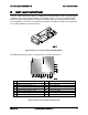
7.3 Control Panel Connectors
The control panel has two external I/O connectors:
One USB port
One VGA video port
The following tables provide the pin-outs for each connector.
Table 47. External USB Connectors (J2D1)
Pin #
Description
1
PWR_FP_USB2
2
USB_DN2_FP_R
3
USB_DP2_FP_R
4
GND
5
GND
6
GND
7
GND
Table 48. Video Connector (J1D1)
Description
Pin #
Pin #
Description
VGA_RED
1
9
GND
VGA_GREEN
2
10
GND
VGA_BLUE
3
11
Unused
Unused
4
12
VGA_DDCDAT
GND
5
13
VGA_HSYNC_L
GND
6
14
VGA_VSYNC_L
VGA_INUSE_L
7
15
VGA_DDCCLK
GND
8
16
GND
17
GND
If a monitor is connected to the control panel video connector, the rear video port on the server
board is disabled and the control panel video is enabled. The video source is the same for both
connectors and is switched between the two, with the rear video having priority over the control
panel. This provides easy front access to the server.