
Service Guide


14 Intel® Server System SR2600UR/SR2625UR Service Guide
Intel
®
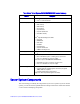
Light-Guided Diagnostics
The server system contains the following diagnostic LEDs, each providing the following
functions:
•
The System Status LED on the front and back panels (see Figure 5 and Figure 8)
shows the overall health of the system (green, blinking green, blinking amber,
amber, off) .
•
The System Identification LED on the front and back panel (see Figure 5 and
Figure 8) helps identify the server from among several servers. The ID LED is off
by default, and blue when activated by button or software.
•
DIMM Fault LEDs on the server board (see Figure 5) help identify failed and failing
DIMM slots. The DIMM fault LEDs turn on (amber) if there is a DIMM fault.
•
POST Code Diagnostic LEDs on the server board (see Figure 5) change color or
state (off, green, red, amber) according to the POST sequence.
•
The 5V-STBY LED on the server board (see Figure 5) is illuminated (green) when
AC power is applied.
•
Fan Fault LEDs on the passive midplane (in the passive system - see Figure 6) or
active midplane (in the active system - see Figure 7) help identify failed and failing
fans. The fan fault LEDs turn on (amber) if there is a fan fault.