Intel® Workstation Board S5520SC Technical Product Specification Intel order number: E39530-010 Revision 1.
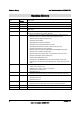
Revision History Intel® Workstation Board S5520SC TPS Revision History Date Revision Number Modifications February 2008 0.1 Preliminary draft April 2008 0.5 Content update April 2008 0.55 Content update September 2008 0.6 Memory upgrade rule updated; product code updated; and added pin-out of internal video header February 2009 1.0 March 2009 1.1 Updated Functional Architecture Section; updated Regulatory and Certification Information; and added Platform Specific Appendix.
Intel® Workstation Board S5520SC TPS Disclaimers Disclaimers Information in this document is provided in connection with Intel® products. No license, express or implied, by estoppel or otherwise, to any intellectual property rights is granted by this document.
Table of Contents Intel® Workstation Board S5520SC TPS Table of Contents 1. 2. 3. Introduction .......................................................................................................................... 1 1.1 Chapter Outline ........................................................................................................ 1 1.2 Workstation Board Use Disclaimer .......................................................................... 1 Overview .................................
Intel® Workstation Board S5520SC TPS 3.3.6 Memory Test .......................................................................................................... 29 3.3.7 Memory Scrub Engine ........................................................................................... 29 3.3.8 Memory RAS ......................................................................................................... 29 3.3.9 Memory Population and Upgrade Rules ..................................................
Table of Contents 4.2 Enabling Advanced Management Features ........................................................... 56 4.2.2 Keyboard, Video, and Mouse (KVM) Redirection .................................................. 57 4.2.3 Media Redirection .................................................................................................. 57 4.2.4 Web Services for Management (WS-MAN) ........................................................... 58 4.2.5 Embedded Web server ................
Intel® Workstation Board S5520SC TPS 7. 6.6 Audio Connectors ................................................................................................ 114 6.7 Onboard Video Header ........................................................................................ 114 6.8 Fan Headers ........................................................................................................ 115 Jumper Blocks .....................................................................................
Table of Contents Intel® Workstation Board S5520SC TPS 10.2 Product Regulatory Compliance Markings .......................................................... 139 10.3 Electromagnetic Compatibility Notices ................................................................ 139 FCC (USA) ......................................................................................................................... 139 ICES-003 (Canada) ..............................................................................
Intel® Workstation Board S5520SC TPS List of Figures List of Figures Figure 1. Intel® Workstation Board S5520SC Layout.................................................................... 5 Figure 2. Intel® Workstation Board S5520SC Connector and Components Layout...................... 6 Figure 3. Major Board Components .............................................................................................. 7 Figure 4. Intel® Workstation Board S5520SC – Mounting Hole Positions........................
List of Figures Intel® Workstation Board S5520SC TPS Figure 33. Setup Utility — Server Management System Information Screen Display ................ 93 Figure 34. Setup Utility — Boot Options Screen Display ............................................................ 94 Figure 35. Setup Utility — Add New Boot Option Screen Display .............................................. 96 Figure 36. Setup Utility — Delete Boot Option Screen Display .................................................. 97 Figure 37.
Intel® Workstation Board S5520SC TPS List of Tables List of Tables Table 1. IOH High-Level Summary ............................................................................................. 17 Table 2. Mixed Processor Configurations ................................................................................... 19 Table 3. Memory Running Frequency vs. Processor SKU.......................................................... 26 Table 4. Memory Running Frequency vs. Memory Population ..................
List of Tables Intel® Workstation Board S5520SC TPS Table 33. Setup Utility — Console Redirection Configuration Fields .......................................... 92 Table 34. Setup Utility — Server Management System Information Fields ................................ 93 Table 35. Setup Utility — Boot Options Screen Fields ............................................................... 95 Table 36. Setup Utility — Add New Boot Option Fields ..............................................................
Intel® Workstation Board S5520SC TPS List of Tables Table 68. Internal Front Panel Audio Header Pin-out (J1D2) ................................................... 114 Table 69. Internal S/PDIF Header Pin-out (J4C1) .................................................................... 114 Table 70. Onboard Video Header Pin-out (J3B2) ..................................................................... 115 Table 71. SSI 4-pin Fan Header Pin-out (J7K1, J9A2, J5B1) ............................................
List of Tables Intel® Workstation Board S5520SC TPS xiv Revision 1.
Intel® Workstation Board S5520SC TPS 1. Introduction Introduction This Technical Product Specification (TPS) provides board-specific information detailing the features, functionality, and high-level architecture of the Intel® Workstation Board S5520SC. In addition, you can obtain design-level information for specific subsystems by ordering the External Product Specifications (EPS) or External Design Specifications (EDS) for a given subsystem.
Overview 2. Intel® Workstation Board S5520SC TPS Overview The Intel® Workstation Board S5520SC is a monolithic printed circuit board (PCB) with features designed to support the performance workstation market. 2.1 Intel® Workstation Board S5520SC Feature Set Feature Processor Description • Support for one or two Intel® Xeon® Processor 5500 series up to 130W Thermal Design Power • Support for one or two Intel® Xeon® Processor(s) 5600 series up to 130W Thermal Design Power • 4.8 GT/s, 5.86 GT/s, and 6.
Intel® Workstation Board S5520SC TPS Feature RAID Support Overview Description • Intel® Embedded Server RAID Technology II through onboard SATA connectors provides SATA RAID 0, 1, and 10 with optional RAID 5 support provided by the Intel® RAID Activation Key AXXRAKSW5 • Intel® Embedded Server RAID Technology II through optional Intel® SAS Entry RAID Module AXX4SASMOD provides SAS RAID 0, 1, and 10 with optional RAID 5 support provided by the Intel® RAID Activation Key AXXRAKSW5 • IT/IR RAID through option
Overview Feature Server Management Intel® Workstation Board S5520SC TPS Description • Onboard ServerEngines* LLC Pilot II* Controller Integrated Baseboard Management Controller (Integrated BMC), IPMI 2.0 compliant Integrated Super I/O on LPC interface • Support for Intel® Remote Management Module 3 • Intel® Light-Guided Diagnostics on field replaceable units • Support for Intel® System Management Software 3.
Intel® Workstation Board S5520SC TPS 2.2 Overview Workstation Board Layout Figure 1. Intel® Workstation Board S5520SC Layout 2.2.1 Workstation Board Connector and Component Layout The following figure shows the board layout of the workstation board. Each connector and major component is identified by a number or letter, and a description follows each figure. Revision 1.
Overview Intel® Workstation Board S5520SC TPS Figure 2. Intel® Workstation Board S5520SC Connector and Components Layout 6 Revision 1.
Intel® Workstation Board S5520SC TPS Overview Callout A Description S/PDIF Header Callout X Description System Fan 3 Header B Slot 1, 32-bit/33-MHz PCI, 5V Y System Fan 4 Header C Intel® Remote Management 3 Slot Z System Fan 2 Header D Slot 2, PCI Express* Gen1 x4 (x8 Mechanically) AA System Fan 1 Header E IEEE 1394a Header BB Main Power Connector F Slot 3, PCI Express* Gen1 x1 (x4 Mechanically) CC LCP/IPMB header G Low-profile USB Solid State Drive Header DD SATA SGPIO Header
Overview 2.2.2 Intel® Workstation Board S5520SC TPS Workstation Board Mechanical Drawings Figure 4. Intel® Workstation Board S5520SC – Mounting Hole Positions 8 Revision 1.
Intel® Workstation Board S5520SC TPS Overview Figure 5. Intel® Workstation Board S5520SC – Major Connector Pin-1 Locations (1 of 2) Revision 1.
Overview Intel® Workstation Board S5520SC TPS Figure 6. Intel® Workstation Board S5520SC – Major Connector Pin-1 Locations (2 of 2) 10 Revision 1.
Intel® Workstation Board S5520SC TPS Overview Figure 7. Intel® Workstation Board S5520SC – Primary Side Keepout Zone (1 of 2) Figure 8. Intel® Workstation Board S5520SC – Primary Side Keepout Zone (2 of 2) Revision 1.
Overview Intel® Workstation Board S5520SC TPS Figure 9. Intel® Workstation Board S5520SC – Primary Side Air Duct Keepout Zone 12 Revision 1.
Intel® Workstation Board S5520SC TPS Overview Figure 10. Intel® Workstation Board S5520SC – Primary Side Card-Side Keepout Zone Revision 1.
Overview Intel® Workstation Board S5520SC TPS Figure 11. Intel® Workstation Board S5520SC – Second Side Keepout Zone 14 Revision 1.
Intel® Workstation Board S5520SC TPS 2.2.3 Overview Workstation Board Rear I/O Layout The following figure shows the layout of the rear I/O components for the workstation board.
Functional Architecture 3. Intel® Workstation Board S5520SC TPS Functional Architecture The architecture and design of the Intel® Workstation Board S5520SC is based on the Intel® 5520 and ICH10R chipset. The chipset is designed for systems based on the Intel® Xeon® Processor 5500 Series in an FC-LGA 1366 Socket B package with Intel® QuickPath Interconnect (Intel® QPI) speed at 6.40 GT/s, 5.86 GT/s, and 4.80 GT/s.
Intel® Workstation Board S5520SC TPS 3.
Functional Architecture 3.1.3 Intel® Workstation Board S5520SC TPS Enterprise South Bridge Interface (ESI) One x4 ESI link interface that supports the PCI Express* Gen1 (2.5 Gbps) transfer rate for connecting Intel® ICH10R in the Intel® Workstation Board S5520SC. 3.1.4 Manageability Engine (ME) An embedded ARC controller is within the IOH providing the Intel® Server Platform Services (SPS). The controller is also commonly referred to as the Manageability Engine (ME). 3.1.
Intel® Workstation Board S5520SC TPS 3.2.2 Functional Architecture Mixed Processor Configurations. The following table describes mixed processor conditions and recommended actions for the Intel® Workstation Board S5520SC. Errors fall into one of three categories: Halt: If the system can boot, it pauses at a blank screen with the text “Unrecoverable fatal error found.
Functional Architecture Error Intel® Workstation Board S5520SC TPS Severity Processor frequency (speed) not identical Halt System Action The BIOS detects the error condition and responds as follows: – Adjusts all processor frequencies to the highest common frequency. – No error is generated – this is not an error condition. – Continues to boot the system successfully. If the frequencies for all processors cannot be adjusted to be the same, then the BIOS: – Logs the error into the SEL.
Intel® Workstation Board S5520SC TPS 3.2.5 Functional Architecture Intel® Turbo Boost Technology Intel® Turbo Boost Technology opportunistically and automatically allows the processor to run faster than the marked frequency if the part is operating below power, temperature, and current limits. If the processor supports this feature, the BIOS setup provides an option to enable or disable this feature. The default is enabled. 3.2.
Functional Architecture Intel® Workstation Board S5520SC TPS The Unified Backplate Assembly is removable, allowing for the use of non-Intel® heatsink retention solutions. Figure 14. Unified Retention System and Unified Back Plate Assembly 3.3 Memory Subsystem The Intel® Xeon® Processor 5500 Series on the Intel® Workstation Board S5520SC are populated on CPU sockets.
Intel® Workstation Board S5520SC TPS Functional Architecture processor configuration. Refer to Figure 15 for the Intel® Workstation Board S5520SC DIMM slots arrangement. Workstation Board CPU Socket CPU 1 Intel® Workstation Board S5520SC CPU 2 Revision 1.
Functional Architecture Workstation Board Intel® Workstation Board S5520SC TPS CPU Socket DIMM Identifier F2 (Black) Channel/Slot Channel F, Slot 1 Figure 15. Intel® Workstation Board S5520SC DIMM Slots Arrangement 3.3.2 Supported Memory Intel® Workstation Board S5520SC supports up to 12 DDR3 DIMMs with 1.5 V and a maximum of 192 GB memory capacity. Intel® Workstation Board S5520SC supports Registered DDR3 DIMMs (RDIMMs), and ECC Unbuffered DDR3 DIMMs (UDIMMs).
Intel® Workstation Board S5520SC TPS Functional Architecture In addition, rules in the following tables (Tables 3 and 4) also determine the global common memory system frequency. Revision 1.
Functional Architecture Intel® Workstation Board S5520SC TPS Table 3. Memory Running Frequency vs. Processor SKU DIMM Type DDR3 800 DDR3 1066 DDR3 1333 800 800 800 800 Processor Integrated Memory Controller (IMC) Max. Frequency (Hz) 1066 800 1066 1066 1333 800 1066 1333 Memory Running Frequency (Hz) = Fastest Common Frequency of Processor IMC and Memory Table 4. Memory Running Frequency vs.
Intel® Workstation Board S5520SC TPS DIMM Type DIMM Populated Per Channel Functional Architecture Memory Running Frequency (Y/N) 800MHz 1066MHz Ranks Per DIMM 1333MHz Command/Add ress Rate SR: Single-Rank DR: Dual-Rank QR: Quad-Rank of processor IMCs and installed memory: 800 MHz, 1066 MHz , or 1333 MHz w/ or w/o ECC UDIMM w/ or w/o ECC Description 2 Y Y N 2N SR or DR All UDIMMs run at 800 MHz or 1066 MHz when two UDIMMs (Single- or Dual-Rank) are installed in the same channel.
Functional Architecture 3.3.4 Intel® Workstation Board S5520SC TPS Publishing System Memory The BIOS displays the “Total Memory” of the system during POST if Quiet Boot is disabled in the BIOS Setup. This is the total size of memory discovered by the BIOS during POST, and is the sum of the individual sizes of installed DDR3 DIMMs in the system. The BIOS also provides the total memory of the system in the BIOS setup (Main page and Advanced | Memory Configuration Page).
Intel® Workstation Board S5520SC TPS Functional Architecture Bank Interleaving – Interleave cache-line data between participant ranks. Channel Interleaving – Interleave between the channel when not in Mirrored Channel Mode. Socket Interleaving – Interleaved memory can spread between both CPU sockets when NUMA mode is disabled, given both CPU sockets are populated and DDR3 DIMMs are installed in slots for both sockets. 3.3.6 Memory Test 3.3.6.
Functional Architecture 3.3.8.2 Intel® Workstation Board S5520SC TPS Independent Channel Mode In the Independent Channel mode, you can populate multiple channels on any channel in any order. The Independent Channel mode provides less RAS capability but better DIMM isolation in case of errors. Moreover, it allows the best interleave mode possible and thereby increases performance and thermal characteristics.
Intel® Workstation Board S5520SC TPS Functional Architecture Optimization techniques used by the Intel® Xeon® Processor 5500 Series to maximize memory bandwidth In the Independent Channel mode, all the DDR3 channels operate independently. Also, you can use the Independent Channel mode to support single DIMM configuration in channel A and in the Single Channel mode.
Functional Architecture Intel® Workstation Board S5520SC TPS 14. The minimal population upgrade recommended for enabling CPU 2 socket are DIMM_A1 and DIMM_D1. In this configuration, only the Independent Channel mode is supported. 15. In the Mirrored Channel mode, memory population on Channel A and B should be identical, including across adjacent slots on the channels, memory population on channels D and E should be identical, including across adjacent slots on the channels.
Intel® Workstation Board S5520SC TPS Functional Architecture Table 5.
Functional Architecture 3.3.11 Intel® Workstation Board S5520SC TPS Memory Error Handling The BIOS classifies memory errors into the following categories: 34 Correctable ECC errors: This correction could be the result of an ECC correction, a successfully retried memory cycle, or both. Unrecoverable/Fatal ECC Errors: The ECC engine detects these errors but cannot correct them.
Intel® Workstation Board S5520SC TPS 3.4 Functional Architecture ICH10R The ICH10R provides extensive I/O support. Functions and capabilities include: PCI Express* Base Specification, Revision 1.1 support PCI Local Bus Specification, Revision 2.3 support for 33-MHz PCI operations (supports up to four REQ#/GNT# pairs) ACPI Power Management Logic Support, Revision 3.
Functional Architecture • • 36 Intel® Workstation Board S5520SC TPS Intel® Embedded Server RAID Technology II drivers, most recent revision At least two SATA hard disk drives Revision 1.
Intel® Workstation Board S5520SC TPS 3.4.1.1.1 Functional Architecture Intel® Embedded Server RAID Technology II Option ROM The Intel® Embedded Server RAID Technology II for SATA Option ROM provides a pre-operating system user interface for the Intel® Embedded Server RAID Technology II implementation and provides the ability to use an Intel® Embedded Server RAID Technology II volume as a boot disk and detect any faults in the Intel® Embedded Server RAID Technology II volume(s). 3.4.1.
Functional Architecture 3.4.2 Intel® Workstation Board S5520SC TPS USB 2.0 Support The USB controller functionality integrated into the ICH10R provides the workstation board with an interface for up to 10 USB 2.0 ports. All ports are high-speed, full-speed, and low-speed capable. • • Four external connectors are located on the back edge of the workstation board. Two internal 2x5 headers (J1D1 and J1D4) are provided; each is capable of supporting two optional USB 2.0 ports.
Intel® Workstation Board S5520SC TPS PCI Bus Segment PE5 Functional Architecture Voltage 3.3 V Width X1 Speed 2.5 Gb/s Type PCI Express* Gen1 PCI I/O Card Slots x1 PCI Express* Gen1 throughput to onboard Integrated BMC 3.3 V X1 2.5 Gb/s PCI Express* Gen1 x1 PCI Express* Gen 1 throughput to Slot 3 (x4 Mechanically) 3.3 V x4 10 Gb/s PCI Express* Gen1 x4 PCI Express* Gen1 throughput to onboard NIC (82575EB) 3.
Functional Architecture Intel® Workstation Board S5520SC TPS Figure 16. Intel® SAS Entry RAID Module AXX4SASMOD Component and Connector Layout 3.6.1 SAS RAID Support The BIOS Setup Utility provides drive configuration options on the Advanced | Mass Storage Controller Configuration setup page for the Intel® SAS Entry RAID Module AXX4SASMOD, some of which affect the ability to configure RAID.
Intel® Workstation Board S5520SC TPS 3.6.1.1 Functional Architecture IT/IR RAID Mode Supports entry hardware RAID 0, RAID 1, and RAID 1E and native SAS pass through mode. Intel® ESRTII Mode 3.6.1.2 The Intel® Embedded Server RAID Technology II (Intel® ESRTII) feature provides RAID modes 0, 1, and 10. If RAID 5 is needed with Intel® ESRTII, you must install the optional Intel® RAID Activation Key AXXRAKSW5 accessory.
Functional Architecture • Intel® Workstation Board S5520SC TPS SMI and PME support The BMC also contains an integrated KVMS subsystem and graphics controller with the following features: • USB 2.0 for Keyboard, Mouse, and Storage devices • • USB 1.1 interface for legacy PS/2 to USB bridging. Hardware Video Compression for text and graphics • • Hardware encryption 2D Graphics Acceleration • • DDR2 graphics memory interface Up to 1600x1200 pixel resolution • PCI Express* x1 support Figure 17.
Intel® Workstation Board S5520SC TPS Functional Architecture Interface 1: This interface is available from either of the available NIC ports in system that can be shared with the host. Only one NIC may be enabled for management traffic at any time. The default active interface is onboard NIC1. Interface 2: This interface is available from Intel® Remote Management Module 3 (Intel® RMM3), which is a dedicated management NIC and not shared with the host.
Functional Architecture RJ-45 Pins 6 7 8 Intel® Workstation Board S5520SC TPS Signal Received Data DCD or DSR Clear To Send Abbreviation RD DCD/DSR CTS DB9 pins 2 1 or 6 (refer note) 8 Note: The RJ45-to-DB9 adapter should match the configuration of the serial device used. One of two pin-out configurations is used, depending on whether the serial device requires a DSR or DCD signal.
Intel® Workstation Board S5520SC TPS Functional Architecture Setup Utility or when an add-in video card is detected. The system BIOS provides the option for Dual Monitor Video operation when an add-in video card is configured in the system. 3.11.1 Video Modes The integrated video controller supports all standard IBM* VGA modes. The following table shows the 2D modes supported for both CRT and LCD. Table 13.
Functional Architecture 3.11.3 Intel® Workstation Board S5520SC TPS Graphics Card Population Guide Table 14. Graphics Card Population Compatible Intel® Server Chassis Intel® Server Chassis SC5600BASE Intel® Server Chassis SC5650WS Graphics Card Support One graphics card with maximum 150-W power in PCI Express* slot 6 One graphics card with maximum 300-W power in PCI Express* slot 6, or up to two graphics cards with maximum 150-W power in PCI Express* slots 4 and 6.
Intel® Workstation Board S5520SC TPS 3.12.1 Functional Architecture MAC Address Definition ® Each Intel Workstation Board S5520SC has the following four MAC addresses assigned to it at the Intel factory.
Functional Architecture Intel® Workstation Board S5520SC TPS 3.13 Audio Codec The workstation board supports the Intel® High Definition audio subsystem based on the Realtek* ALC889 audio codex. The feature list for the ALC889 is as follows: High-performance DACs with 108dB signal-to-noise ratio (A-weighting) High-performance ADCs with 104dB signal-to-noise ration (A-weighting) Meets Microsoft* WLP3.0x and future WLP4.
Intel® Workstation Board S5520SC TPS Functional Architecture 3.14 IEEE 1394a Support The Intel® Workstation Board S5520SC provides two IEEE 1394a ports via a Texas Instruments* TSB43AB22A: an external 6-pin IEEE 1394a port through rear I/O panel and an internal 2x5 pin IEEE 1394a port. Both of the 1394 ports are capable of transferring data between the 32-bit/33-MHz PCI bus and the 1394 bus at 100M bits/s, 200M bits/s, and 400M bits/s.
Functional Architecture Intel® Workstation Board S5520SC TPS PCI and CardBus register support Isochronous receive dual-buffer mode Out-of-order pipelining for asynchronous transmit requests Register access fail interrupt when the PHY SCLK is not active PCI power-management D0, D1, D2, and D3 power states Initial bandwidth available and initial channels available registers PME support per 1394 Open Host Controller Interface Specification 3.15 Trusted Platform Module (TPM) 3.15.
Intel® Workstation Board S5520SC TPS Functional Architecture administrative command requests. - Provides BIOS Setup options to change TPM security states and to clear TPM ownership. For additional details, refer to the TCG PC Client Specific Implementation Specification, the TCG PC Client Specific Physical Presence Interface Specification, and the Microsoft BitLocker* Requirement documents. 3.15.2.
Functional Architecture Main Intel® Workstation Board S5520SC TPS Advanced Security Server Management Administrator Password Status User Password Status Set Administrator Password [1234aBcD] Set User Password [1234aBcD] Front Panel Lockout Enabled/Disabled TPM State TPM Administrative Control Boot Options Boot Manager No Operation/Turn On/Turn Off/Cle
Intel® Workstation Board S5520SC TPS Functional Architecture 3.16 ACPI Support The Intel® Workstation Board supports S0, S1, S3, and S5 states. S1 is considered a sleep state. The wake-up sources are enabled by the ACPI operating systems with cooperation from the drivers; the BIOS has no direct control over the wake-up sources when an ACPI operating system is loaded. The role of the BIOS is limited to describing the wake-up sources to the operating system.
Platform Management 4. Intel® Workstation Board S5520SC TPS Platform Management The platform management subsystem is based on the Integrated BMC features of the ServerEngines* Pilot II. The onboard platform management subsystem consists of communication buses, sensors, and the system BIOS, and server management firmware. Figure 19 provides an illustration of the Server Management Bus (SMBUS) architecture as used on these server boards. 4.1 Feature Support 4.1.1 IPMI 2.
Intel® Workstation Board S5520SC TPS Platform Management Chassis intrusion detection (dependant on platform support) Basic fan control using TControl version 2 SDRs Fan redundancy monitoring and support Power supply redundancy monitoring and support Hot swap fan support Acoustic management: Supports multiple fan profiles Signal testing support: The BMC provides test commands for setting and getting platform signal states.
Platform Management 4.2 Intel® Workstation Board S5520SC TPS Optional Advanced Management Feature Support This section explains the advanced management features supported by the BMC firmware. Table 13 lists basic and advanced feature support. Individual features may vary by platform. For more information, refer to Appendix C. Table 17. Basic and Advanced Management Features Feature IPMI 2.
Intel® Workstation Board S5520SC TPS 4.2.2 Platform Management Keyboard, Video, and Mouse (KVM) Redirection The advanced management features include support for keyboard, video, and mouse redirection (KVM) over LAN. This feature is available remotely from the embedded web server as a Java* applet. The client system must have a Java Runtime Environment (JRE) Version 1.6 (JRE6) or later to run the KVM or media redirection applets.
Platform Management Intel® Workstation Board S5520SC TPS The following capabilities are supported: The operation of remotely mounted devices is independent of the local devices on the server. Both remote and local devices are usable in parallel. You can mount either IDE (CD-ROM, floppy) or USB devices as a remote device to the server. It is possible to boot all supported operating systems from the remotely mounted device and to boot from disk IMAGE (*.IMG) and CD-ROM or DVD-ROM ISO files.
Intel® Workstation Board S5520SC TPS Platform Management Note: WS-MAN features will be made available after production launch. 4.2.5 Embedded Web server The BMC provides an embedded web server for out-of-band management. User authentication is handled by IPMI user names and passwords. Base functionality for the embedded web server includes: Power Control Sensor Reading SEL Reading KVM/Media Redirection: Only available when the Intel® RMM3 is present.
Platform Management 4.3 Intel® Workstation Board S5520SC TPS Platform Control This server platform has embedded platform control which is capable of automatically adjusting system performance and acoustic levels.
Intel® Workstation Board S5520SC TPS 4.3.1 Platform Management Memory Open and Closed Loop Thermal Throttling Open-Loop Thermal Throttling (OLTT) Throttling is a solution to cool the DIMMs by reducing memory traffic allowed on the memory bus, which reduces power consumption and thermal output. With OLTT, the system throttles in response to memory bandwidth demands instead of actual memory temperature.
Platform Management Intel® Workstation Board S5520SC TPS BIOS fails to get the Thermal SDRs, then it uses the Memory Reference Code (MRC) default settings for the memory throttling settings. The BIOS Setup Utility provides options to set the fan profile or operating mode the platform will operate under. Each operating mode has a predefined profile for which specific platform targets are configured, which in turn determines how the system fans operate to meet those targets.
Intel® Workstation Board S5520SC TPS 4.3.2.3.1 Platform Management Performance Mode (Default) With the platform running in Performance mode (Default), several platform control algorithm variables are set to enhance the platform’s capability of operating at maximum performance targets for the given system. In doing so, the platform is programmed with higher fan speeds at lower ambient temperatures.
Platform Management 4.4 Intel® Workstation Board S5520SC TPS Intel® Intelligent Power Node Manager Intel® Intelligent Power Node Manager is a platform (system)-level solution that provides the system with a method of monitoring power consumption and thermal output, and adjusting system variables to control those factors. The BMC supports Intel® Intelligent Power Node Manager specification version 1.5.
Intel® Workstation Board S5520SC TPS Platform Management Figure 19. SMBUS Block Diagram Revision 1.
BIOS Setup Utility Intel® Workstation Board S5520SC TPS 5. BIOS Setup Utility 5.1 Logo/Diagnostic Screen The Logo/Diagnostic Screen displays in one of two forms: If Quiet Boot is enabled in the BIOS setup, a logo splash screen displays. By default, Quiet Boot is enabled in the BIOS setup. If the logo displays during POST, press to hide the logo and display the diagnostic screen.
Intel® Workstation Board S5520SC TPS 5.3.1 BIOS Setup Utility Operation The BIOS Setup has the following features: Localization - The BIOS Setup uses the Unicode standard and is capable of displaying setup forms in all languages currently included in the Unicode standard. The Intel® workstation BIOS is only available in English. Console Redirection - The BIOS Setup is functional via console redirection over various terminal emulation standards.
BIOS Setup Utility Intel® Workstation Board S5520SC TPS Each Setup menu page contains a number of features. Each feature is associated with a value field except those used for informative purposes. Each value field contains configurable parameters. Depending on the security option selected and (in effect) by the password, a menu feature’s value may or may not change. If a value cannot be changed, its field is made inaccessible and appears grayed out. Table 20.
Intel® Workstation Board S5520SC TPS Key Option Save and Exit BIOS Setup Utility Description Pressing causes the following message to display: Save configuration and reset? Yes No If “Yes” is highlighted and is pressed, all changes are saved and the Setup is exited. If “No” is highlighted and is pressed, or the key is pressed, the user is returned to where they were before was pressed without affecting any existing values. 5.3.1.
BIOS Setup Utility 5.3.2.1 Intel® Workstation Board S5520SC TPS Main Screen Unless an error occurred, the Main screen is the first screen displayed when the BIOS Setup is entered. If an error occurred, the Error Manager screen displays instead. Main Advanced Security Server Management Boot Options Boot Manager Logged in as Platform ID System BIOS Version S5500.86B.xx.yy.
Intel® Workstation Board S5520SC TPS Setup Item Build Date Options BIOS Setup Utility Help Text Comments Information only. Displays the current BIOS build date. Memory Size Quiet Boot Information only. Displays the total physical memory installed in the system in MB or GB. The term physical memory indicates the total memory discovered in the form of installed DDR3 DIMMs. Enabled Disabled [Enabled] – Display the logo screen during POST. [Disabled] – Display the diagnostic screen during POST.
BIOS Setup Utility 5.3.2.2 Intel® Workstation Board S5520SC TPS Advanced Screen The Advanced screen provides an access point to configure several options. On this screen, the user selects the option they want to configure. Configurations are performed on the selected screen and not directly on the Advanced screen. To access this screen from the Main screen, press the right arrow until the Advanced screen is selected.
Intel® Workstation Board S5520SC TPS 5.3.2.2.1 BIOS Setup Utility Processor Screen The Processor screen allows the user to view the processor core frequency, system bus frequency, and to enable or disable several processor options. This screen also allows the user to view information about a specific processor. To access this screen from the Main screen, select Advanced > Processor.
BIOS Setup Utility Intel® Workstation Board S5520SC TPS Table 23. Setup Utility — Processor Configuration Screen Fields Setup Item Processor ID Options Help Text Comments Information only. Processor CPUID. Processor Frequency Information only. Current frequency of the processor. Microcode Revision Information only. Revision of the loaded microcode. L1 Cache RAM Information only. Size of the Processor L1 Cache. L2 Cache RAM Information only. Size of the Processor L2 Cache.
Intel® Workstation Board S5520SC TPS Setup Item Intel® Virtualization Technology Options Enabled Disabled BIOS Setup Utility Help Text Intel® Virtualization Technology allows a platform to run multiple operating systems and applications in independent partitions. Comments Note: A change to this option requires the system to be powered off and then back on before the setting takes effect.
BIOS Setup Utility 5.3.2.2.2 Intel® Workstation Board S5520SC TPS Memory Screen The Memory screen allows the user to view details about the system memory DDR3 DIMMs installed. This screen also allows the user to open the Configure Memory RAS and Performance screen. To access this screen from the Main screen, select Advanced > Memory.
Intel® Workstation Board S5520SC TPS BIOS Setup Utility Table 24. Setup Utility — Memory Configuration Screen Fields Setup Item Total Memory Options Help Text Effective Memory Comments Information only. The amount of memory available in the system in the form of installed DDR3 DIMMs in units of MB or GB. Information only. The amount of memory available to the operating system in MB or GB.
BIOS Setup Utility Intel® Workstation Board S5520SC TPS 5.3.2.2.2.1 Configure Memory RAS and Performance Screen The Configure Memory RAS and Performance screen allows the user to customize several memory configuration options, such as whether to use Memory Mirroring. To access this screen from the Main screen, select Advanced > Memory > Configure Memory RAS and Performance.
Intel® Workstation Board S5520SC TPS 5.3.2.2.3 BIOS Setup Utility Mass Storage Controller Screen The Mass Storage screen allows the user to configure the SATA/SAS controller when it is present on the baseboard, module card of an Intel system. To access this screen from the Main menu, select Advanced > Mass Storage.
BIOS Setup Utility Intel® Workstation Board S5520SC TPS Table 26. Setup Utility — Mass Storage Controller Configuration Screen Fields Setup Item Intel® Entry SAS RAID Module Options Enabled Disabled Help Text Enabled or Disable the Intel® SAS Entry RAID Module Comments Unavailable if the SAS Module (AXX4SASMOD) is not present.
Intel® Workstation Board S5520SC TPS 5.3.2.2.4 BIOS Setup Utility Serial Ports Screen The Serial Ports screen allows the user to configure the Serial A [COM 1] and Serial B [COM2] ports. To access this screen from the Main screen, select Advanced > Serial Port. Advanced Serial Port Configuration Serial A Enable Enabled/Disabled Address 3F8h/2F8h/3E8h/2E8h IRQ 3 or 4 Serial B Enable Enabled/Disabled Address 3F8h/2F8h/3E8h/2E8h IRQ 3 or 4 Figure 26.
BIOS Setup Utility 5.3.2.2.5 Intel® Workstation Board S5520SC TPS USB Configuration Screen The USB Configuration screen allows the user to configure the USB controller options. To access this screen from the Main screen, select Advanced > USB Configuration.
Intel® Workstation Board S5520SC TPS BIOS Setup Utility Table 28. Setup Utility — USB Controller Configuration Screen Fields Setup Item Detected USB Devices Options Help Text USB Controller Enabled [Enabled] - All onboard USB controllers are turned on and accessible by the OS. Disabled Comments Information only. Shows the number of USB devices in the system. [Disabled] - All onboard USB controllers are turned off and inaccessible by the OS.
BIOS Setup Utility 5.3.2.2.6 Intel® Workstation Board S5520SC TPS PCI Screen The PCI Screen allows the user to configure the PCI add-in cards, onboard NIC controllers, and video options. To access this screen from the Main screen, select Advanced > PCI.
Intel® Workstation Board S5520SC TPS Setup Item Onboard NIC2 ROM Options Enabled Disabled Help Text If enabled. loads the embedded option ROM for the onboard network controllers. BIOS Setup Utility Comments Warning: If [Disabled] is selected, NIC2 cannot be used to boot or wake the system. Onboard NIC iSCSI ROM Enabled Disabled If enabled. loads the embedded option ROM for the onboard network controllers. Warning: If [Disabled] is selected, NIC1 and NIC2 cannot be used to boot or wake the system.
BIOS Setup Utility 5.3.2.2.7 Intel® Workstation Board S5520SC TPS System Acoustic and Performance Configuration The System Acoustic and Performance Configuration screen allows the user to configure the thermal characteristics of the system. To access this screen from the Main screen, select Advanced > System Acoustic and Performance Configuration.
Intel® Workstation Board S5520SC TPS Main Advanced Security BIOS Setup Utility Server Management Administrator Password Status User Password Status Set Administrator Password [1234aBcD] Set User Password [1234aBcD] Front Panel Lockout Enabled/Disabled TPM State TPM Administrative Control Boot Options Boot Manager No Operation/Turn On/Turn Off/Clear Ow
BIOS Setup Utility Setup Item Front Panel Lockout Intel® Workstation Board S5520SC TPS Options Enabled Help Text If enabled, locks the power button and reset button on the system's front panel. If [Enabled] is selected, power and reset must be controlled via a system management interface. Disabled TPM State Comments Enabled and Activated Information only. Enabled and Deactivated Shows the current TPM device state.
Intel® Workstation Board S5520SC TPS Main Advanced Security BIOS Setup Utility Server Management Boot Options Assert NMI on SERR Enabled/Disabled Assert NMI on PERR Enabled/Disabled Resume on AC Power Loss Stay Off/Last state/Reset Clear System Event Log Enabled/Disabled FRB-2 Enable Enabled/Disabled O/S Boot Watchdog Timer Enabled/Disabled O/S Boot Watchdog Timer Policy Power off/Reset O/S Boot Watchdog Timer Timeout 5 minutes/10 minutes/15 minutes/20 minutes ACPI 1.
BIOS Setup Utility Intel® Workstation Board S5520SC TPS Table 32. Setup Utility — Server Management Configuration Screen Fields Setup Item Assert NMI on SERR Assert NMI on PERR Resume on AC Power Loss Options Enabled Help Text On SERR, generate an NMI and log an error. Disabled Note: [Enabled] must be selected for the Assert NMI on PERR setup option to be visible. Enabled On PERR, generate an NMI and log an error.
Intel® Workstation Board S5520SC TPS 5.3.2.4.1 BIOS Setup Utility Console Redirection Screen The Console Redirection screen allows the user to enable or disable console redirection and configure the connection options for this feature. To access this screen from the Main screen, select Server Management > Console Redirection. Server Management Console Redirection Console Redirection Disabled/Serial Port A/Serial Port B Flow Control None/RTS/CTS Baud Rate 9.6k/19.2k/38.4k/57.6k/115.
BIOS Setup Utility Intel® Workstation Board S5520SC TPS Table 33. Setup Utility — Console Redirection Configuration Fields Setup Item Console Redirection Options Disabled Serial Port A Help Text Console redirection allows a serial port to be used for server management tasks. Serial Port B [Disabled] - No console redirection. [Serial Port A] - Configure serial port A for console redirection. [Serial Port B] - Configure serial port B for console redirection.
Intel® Workstation Board S5520SC TPS 5.3.2.5 BIOS Setup Utility Server Management System Information Screen The Server Management System Information screen allows the user to view part numbers, serial numbers, and firmware revisions. To access this screen from the Main screen, select Server Management > System Information.
BIOS Setup Utility 5.3.2.6 Intel® Workstation Board S5520SC TPS Boot Options Screen The Boot Options screen displays any bootable media encountered during POST and allows the user to configure the desired boot device. To access this screen from the Main screen, select Boot Options.
Intel® Workstation Board S5520SC TPS BIOS Setup Utility Table 35. Setup Utility — Boot Options Screen Fields Setup Item Boot Timeout Options 0 - 65535 Help Text The number of seconds the BIOS should pause at the end of POST to allow the user to press the [F2] key for entering the BIOS Setup utility. Valid values are 0-65535. Zero is the default. A value of 65535 causes the system to go to the Boot Manager menu and wait for user input for every system boot. Boot Option #x Available boot devices.
BIOS Setup Utility Intel® Workstation Board S5520SC TPS If all types of bootable devices are installed in the system, the default boot order is: 1. 2. 3. 4. 5. 6. CD/DVD-ROM Floppy Disk Drive Hard Disk Drive PXE Network Device BEV (Boot Entry Vector) Device EFI Shell and EFI Boot paths 5.3.2.6.1 Add New Boot Option Screen The Add Boot Option screen allows the user to remove an EFI boot option from the boot order. To access this screen from the Main screen, select Boot Options > Delete Boot Options.
Intel® Workstation Board S5520SC TPS 5.3.2.6.2 BIOS Setup Utility Delete Boot Option Screen The Delete Boot Option screen allows the user to remove an EFI boot option from the boot order. Note that while you can delete the Internal EFI Shell in this screen, it is restored to the Boot Order on the next reboot. You cannot permanently delete the Internal EFI Shell. To access this screen from the Main screen, select Boot Options > Delete Boot Options.
BIOS Setup Utility 5.3.2.6.3 Intel® Workstation Board S5520SC TPS Hard Disk Order Screen The Hard Disk Order screen allows the user to control the hard disks. To access this screen from the Main screen, select Boot Options > Hard Disk Order. Boot Options Hard Disk #1 < Available Hard Disks > Hard Disk #2 < Available Hard Disks > Figure 37. Setup Utility — Hard Disk Order Screen Display Table 38. Setup Utility — Hard Disk Order Fields 5.3.2.6.
Intel® Workstation Board S5520SC TPS BIOS Setup Utility Table 39. Setup Utility — CDROM Order Fields Setup Item CDROM #1 Options Available Legacy devices for this Device group. Help Text Set system boot order by selecting the boot option for this position. CDROM #2 Available Legacy devices for this Device group. Set system boot order by selecting the boot option for this position. 5.3.2.6.5 Floppy Order Screen The Floppy Order screen allows the user to control the floppy drives.
BIOS Setup Utility 5.3.2.6.6 Intel® Workstation Board S5520SC TPS Network Device Order Screen The Network Device Order screen allows the user to control the network bootable devices. To access this screen from the Main screen, select Boot Options > Network Device Order. Boot Options Network Device #1 Network Device #2 Figure 40. Setup Utility — Network Device Order Screen Display Table 41.
Intel® Workstation Board S5520SC TPS BIOS Setup Utility Table 42. Setup Utility — BEV Device Order Fields 5.3.2.7 Setup Item BEV Device #1 Options Available Legacy devices for this Device group. Help Text Set system boot order by selecting the boot option for this position. BEV Device #2 Available Legacy devices for this Device group. Set system boot order by selecting the boot option for this position.
BIOS Setup Utility 5.3.2.8 Intel® Workstation Board S5520SC TPS Error Manager Screen The Error Manager screen displays any errors encountered during POST. Error Manager ERROR CODE Exit SEVERITY INSTANCE Figure 43. Setup Utility — Error Manager Screen Display Table 44. Setup Utility — Error Manager Screen Fields Setup Item Displays System Errors 5.3.2.9 Comments Information only. Displays errors that occurred during the POST.
Intel® Workstation Board S5520SC TPS Error Manager BIOS Setup Utility Exit Save Changes and Exit Discard Changes and Exit Save Changes Discard Changes Load Default Values Save as User Default Values Load User Default Values Figure 44. Setup Utility — Exit Screen Display Table 45. Setup Utility — Exit Screen Fields Setup Item Save Changes and Exit Help Text Exit the BIOS Setup utility after saving changes. The system reboots if required.
Connector/Header Locations and Pin-outs Intel® Workstation Board S5520SC TPS 6. Connector/Header Locations and Pin-outs 6.1 Board Connector Information The following section provides detailed information regarding all connectors, headers, and jumpers on the workstation board. The following table lists all connector types available on the board and the corresponding preference designators printed on the silkscreen. Table 46.
Intel® Workstation Board S5520SC TPS Connector Serial port A Configuration Quantity 1 Connector/Header Locations and Pin-outs Reference Designators Connector Type J4B2 Pin Count Jumper 3 Serial port B 1 J1B1 Header 9 Front panel 1 J1B3 Header 24 Internal USB 2 J1D1, J1D4 Header 10 USB_SSD 1 J1D3 Low profile header 10 Internal USB 1 J1H2 Header 4 Chassis Intrusion 1 J2D1 Header 2 Serial ATA 6 J1G1, J1G4, J1G5, J1E3, J1F1, J1F4 Header 7 HSBP 2 J1F5, J1G3 Header 4
Connector/Header Locations and Pin-outs Pin Signal Intel® Workstation Board S5520SC TPS Color Pin Signal Color 10 +12 Vdc Yellow 22 +5 Vdc Red 11 +12 Vdc Yellow 23 +5 Vdc Red 12 +3.3 Vdc Orange 24 GND Black Table 48.
Intel® Workstation Board S5520SC TPS 6.3 Connector/Header Locations and Pin-outs System Management Headers 6.3.1 Intel® Remote Management Module 3 (Intel® RMM3) Connector A 34-pin Intel® RMM3 connector (J1C1) is included on the workstation board to support the optional Intel® Remote Management Module 3. This workstation board does not support thirdparty management cards.
Connector/Header Locations and Pin-outs 6.3.3 Intel® Workstation Board S5520SC TPS HSBP Header Table 53. HSBP Header Pin-out (J1F5, J1G3) Pin 1 Signal Name SMB_IPMB_5V_DAT Description BMC IMB 5V Data Line 2 GND Ground 3 SMB_IPMB_5V_CLK BMC IMB 5V Clock Line P5V – HSBP_A +5V for HSBP A GND – HSBP_B Ground for HSBP B 4 6.3.4 SGPIO Header Table 54. SGPIO Header Pin-out (J1G2) Pin 1 2 3 4 6.
Intel® Workstation Board S5520SC TPS 6.5 Connector/Header Locations and Pin-outs Pin Signal Name Description Pi n Signal Name Description 17 BND (Reset GND) Reset Button Ground 1 8 SMB_SENSOR_3V3 STB_CLK SMB Sensor Clock 19 FP_ID_BTN_N ID Button 2 0 FP_CHASSIS_INTR U Chassis Intrusion 21 FM_SIO_TEMP_SENS OR Front Panel Temperature Sensor 2 2 NIC2_ACT_LED_N NIC 2 Activity LED - 23 FP_NMI_BTN_N NMI Button 2 4 NIC2_LINK_LED_N NIC 2 Link LED - I/O Connectors 6.5.
Connector/Header Locations and Pin-outs Intel® Workstation Board S5520SC TPS Table 57. SATA/SAS Connector Pin-out (J1E3, J1G1, J1G4, J1G5, J1F1, J1F4) Pin 1 6.5.
Intel® Workstation Board S5520SC TPS 6.5.4 Connector/Header Locations and Pin-outs Serial Port Connectors The workstation board provides one external RJ-45 Serial A port (J8A2) and one internal 9-pin Serial B header (J1B1). The following tables define the pin-outs. Table 59.
Connector/Header Locations and Pin-outs Pin 4 Signal Name GND Intel® Workstation Board S5520SC TPS Description Ground Two 2x5 connectors on the workstation board (J1D1, J1D4) provide support for four additional USB ports. Table 62.
Intel® Workstation Board S5520SC TPS Pin 3 Connector/Header Locations and Pin-outs Signal Name USB Data - Description USB port 11 negative signal 4 NC Not Connect 5 USB Data + USB port 11 positive signal 6 NC Not Connect 7 Ground 8 NC Not Connect 9 Key No pin 10 LED# Activity LED One additional Type A USB port (J1H2) is provided on the workstation board to support the installation of a USB device inside the workstation chassis. Table 65. Internal Type A USB Port Pin-out (J1H2) 6.5.
Connector/Header Locations and Pin-outs 6.6 Signal Name Intel® Workstation Board S5520SC TPS Pin 6 TPB+ Description TPB positive signal 7 GND Ground 8 GND Ground 9 TPA- TPA negative signal 10 TPA+ TPA positive signal Audio Connectors The workstation board provides one stacked audio connector on the back edge of the board (J6A1).
Intel® Workstation Board S5520SC TPS Connector/Header Locations and Pin-outs Table 70. Onboard Video Header Pin-out (J3B2) Pin 6.
Connector/Header Locations and Pin-outs Intel® Workstation Board S5520SC TPS Table 72.
Intel® Workstation Board S5520SC TPS 7. Jumper Blocks Jumper Blocks The workstation board has several 3-pin jumper blocks that you can use to configure, protect, or recover specific features of the workstation board. Pin 1 on each jumper block is identified by the following symbol on the silkscreen: ▼ Figure 45. Jumper Blocks Table 73.
Jumper Blocks Intel® Workstation Board S5520SC TPS Jumper Name Pins 2-3 J1H1: Force Update BMC J2C1: CMOS Clear J4B2: Serial Port A Configuration 7.1 System Results The main system BIOS will not boot with pins 2-3 connected. When connected, the system will only boot from EFI-bootable recovery media with a recovery BIOS image present.
Intel® Workstation Board S5520SC TPS Jumper Blocks 8. Close the workstation chassis. 9. Power up the workstation. The password is now cleared and you can reset it by going into the BIOS setup. 7.2 Force BMC Update Procedure When performing a standard BMC (Baseboard Management Controller) firmware update procedure, the update utility places the BMC into an update mode, allowing the firmware to load safely onto the flash device.
Jumper Blocks Intel® Workstation Board S5520SC TPS 3. Move the BIOS recovery jumper (J1E5) from the default operating position (covering pins 1 and 2) to the enabled position (covering pins 2 and 3). 4. Close the workstation chassis. 5. Reconnect the AC power cord and power up the workstation. 6. Perform the BIOS Recovery procedure as documented in the BIOS Release Notes. 7. After successful completion of the BIOS recovery, the “BIOS has been updated successfully” message displays. 8.
Intel® Workstation Board S5520SC TPS 8. Intel® Light Guided Diagnostics Intel® Light Guided Diagnostics The workstation board has several onboard diagnostic LEDs to assist in troubleshooting boardlevel issues. This section provides a description of the location and function of each LED on the workstation board. 8.1 5-V Stand-by LED Several workstation management features of this workstation board require a 5-V stand-by voltage is supplied from the power supply.
Intel® Light Guided Diagnostics Intel® Workstation Board S5520SC TPS Figure 46. 5V Stand-by Status LED Location 8.2 Fan Fault LEDs Fan fault LEDs are present for the two CPU fans and the rear system fan 5. The fan fault LED illuminates when the corresponding fan has fault Figure 47. Fan Fault LED Locations 122 Revision 1.
Intel® Workstation Board S5520SC TPS 8.3 Intel® Light Guided Diagnostics System Status LED and System ID LED The workstation board provides LEDs for both system ID and system status. These LEDs are located in the rear I/O area of the workstation board as shown in the following figure. A. System Status LED B. System ID LED Figure 48.
Intel® Light Guided Diagnostics Intel® Workstation Board S5520SC TPS By issuing the appropriate hex IPMI “Chassis Identify” value, the ID LED either blinks blue for 15 seconds and turns off or blinks indefinitely until the appropriate hex IPMI Chassis Identify value is issued to turn it off. The bi-color (green/amber) System Status LED operates as follows: Table 74. System Status LED Color State Criticality Description Green Solid on System OK System booted and ready.
Intel® Workstation Board S5520SC TPS Intel® Light Guided Diagnostics * When the workstation is powered down (transitions to the DC-off state or S5), the BMC is still on standby power and retains the sensor and front panel status LED state established before the power-down event. If the system status is normal when the system is powered down (the LED is in a solid green state), the system status LED will be off. 8.4 DIMM Fault LEDs The workstation board provides memory fault LED for each DIMM socket.
Intel® Light Guided Diagnostics 8.5 Intel® Workstation Board S5520SC TPS POST Code Diagnostic LEDs Eight amber POST code diagnostic LEDs are located on the back edge of the workstation board in the rear I/O area of the workstation board by the serial A connector. During the system boot process, the BIOS executes a number of platform configuration processes, each of which is assigned a specific hex POST code number.
Intel® Workstation Board S5520SC TPS Design and Environmental Specifications 9. Design and Environmental Specifications 9.1 Intel® Workstation Board S5520SC Design Specifications Operation of the Intel® Workstation Board S5520SC at conditions beyond those listed in the following table may cause permanent damage to the system. Exposure to absolute maximum rating conditions for extended periods may affect system reliability. Table 75.
Design and Environmental Specifications Intel® Workstation Board S5520SC TPS • Calculation Model: Telcordia Issue 1, method I case 3 • Operating Temperature: Server in 30 °C ambient air • • Operating Environment: Ground Benign, Controlled Duty Cycle: 100% • Quality Level: II Table 76. MTBF Estimate S5520SC MTBF (hours) 72,000 91,000 114,000 145,000 184,000 128 Ambient Air Temperature (ºC) Air Temp. at Board for 10(ºC) rise (ºC) 45 40 35 30 25 55 50 45 40 35 Revision 1.
Intel® Workstation Board S5520SC TPS 9.3 Design and Environmental Specifications Workstation Board Power Requirements This section provides power supply design guidelines for a system using the Intel® Workstation Board S5520SC, including voltage and current specifications, and power supply on/off sequencing characteristics. The following diagram shows the power distribution implemented on this workstation board. Revision 1.
Design and Environmental Specifications Intel® Workstation Board S5520SC TPS Figure 51. Power Distribution Block Diagram 130 Intel order number: E39530-010 Revision 1.
Intel® Workstation Board S5520SC TPS 9.3.1 Design and Environmental Specifications Processor Power Support The workstation board supports the Thermal Design Power (TDP) guideline for Intel® Xeon® processors. The Flexible Motherboard Guidelines (FMB) were also followed to determine the suggested thermal and current design values for anticipating future processor needs. The following table provides maximum values for Icc, TDP power and TCASE for the Intel® Xeon® Processor 5500 Series. Table 77.
Design and Environmental Specifications 9.4.2 Intel® Workstation Board S5520SC TPS Stand-by Outputs The 5 VSB output should be present when an AC input is greater than the power supply turn-on voltage is applied. 9.4.3 Remote Sense The power supply should have remote sense return (ReturnS) to regulate out ground drops for all output voltages: +3.3 V, +5 V, +12 V1, +12 V2, +12 V3, +12 V4, -12 V, and 5 VSB. The power supply should use remote sense to regulate out drops in the system for the +3.
Intel® Workstation Board S5520SC TPS 9.4.5 Design and Environmental Specifications Dynamic Loading The output voltages remain within limits for the step loading and capacitive loading specified in the following table. You should test the load transient repetition rate between 50 Hz and 5 kHz at duty cycles ranging from 10% to 90%. The load transient repetition rate is only a test specification. The Δ step load may occur anywhere within the minimum load to the maximum load range. Table 80.
Design and Environmental Specifications 9.4.8 Intel® Workstation Board S5520SC TPS Timing Requirements The following are the timing requirements for the power supply operation. The output voltages must rise from 10% to within regulation limits (Tvout_rise) within 5 ms to 70 ms. 5 VSB is allowed to rise from 1.0 ms to 25 ms. +3.3 V, +5 V, and +12 V output voltages should start to rise approximately at the same time. All outputs must rise monotonically.
Intel® Workstation Board S5520SC TPS Design and Environmental Specifications Table 84. Turn On/Off Timing Item Description Minimum Maximum Units Tsb_on_delay Delay from AC being applied to 5 VSB being within regulation. N/A 1500 ms Tac_on_delay Delay from AC being applied to all output voltages being within N/A regulation. 2500 Tvout_holdup Time all output voltages stay within regulation after loss of AC.
Design and Environmental Specifications Intel® Workstation Board S5520SC TPS AC Input Tvout_holdup Vout Tpwok_low TAC_on_delay Tsb_on_delay PWOK 5VSB Tpwok_off Tpwok_on Tsb_on_delay Tpwok_on Tpwok_off Tpson_pwok Tpwok_holdup T5VSB_holdup Tsb_vout Tpson_on_delay PSON AC turn on/off cycle PSON turn on/off cycle Figure 53. Turn On/Off Timing (Power Supply Signals) 9.4.
Intel® Workstation Board S5520SC TPS Regulatory and Certification Information 10. Regulatory and Certification Information To help ensure EMC compliance with your local regional rules and regulations, before computer integration, make sure that the chassis, power supply, and other modules have passed EMC testing using a workstation board with a microprocessor from the same family (or higher) and operating at the same (or higher) speed as the microprocessor used on this workstation board.
Regulatory and Certification Information • • • • • 10.1.3 • • • • • • • • • 138 Intel® Workstation Board S5520SC TPS BSMI CNS13438 Emissions (Taiwan) RRL Notice No.
Intel® Workstation Board S5520SC TPS Regulatory and Certification Information 10.
Regulatory and Certification Information Intel® Workstation Board S5520SC TPS This equipment has been tested and found to comply with the limits for a Class A digital device, pursuant to Part 15 of the FCC Rules. These limits are designed to provide reasonable protection against harmful interference in a residential installation.
Intel® Workstation Board S5520SC TPS Regulatory and Certification Information ICES-003 (Canada) Cet appareil numérique respecte les limites bruits radioélectriques applicables aux appareils numériques de Classe A prescrites dans lanorme sur le matériel brouilleur: “Apparelis Numériques”, NMB-003 édictee par le Ministre Canadian des Communications.
Regulatory and Certification Information Intel® Workstation Board S5520SC TPS RRL KCC (Korea) 10.4 Product Ecology Change (EU RoHS) Intel has a system in place to restrict the use of banned substances in accordance with the European Directive 2002/95/EC. Compliance is based on declaration that materials banned in the RoHS Directive are either (1) below all applicable threshold limits or (2) an approved/pending RoHS exemption applies. RoHS implementation details are not fully defined and may change.
Intel® Workstation Board S5520SC TPS Regulatory and Certification Information CRoHS Substance Tables: China CRoHS requires products to be provided with controlled substance information. Intel understands the end-seller (entity placing product into market place) is responsible for providing the controlled substance information. Controlled substance information is required to be in Simplified Chinese. Substance table for this board product is as follows: Revision 1.
Regulatory and Certification Information 144 Intel® Workstation Board S5520SC TPS Revision 1.
Intel® Workstation Board S5520SC TPS Regulatory and Certification Information 10.6 China Packaging Recycle Marks (or GB18455-2001) Intel EPSD has the following ecological compliances: Cardboard and fiberboard packaging will be marked as recyclable in China. China Packaging Recycling Marks is required on retail packaging to be marked as recyclable using China’s recycling logo.
Appendix A: Integration and Usage Tips Intel® Workstation Board S5520SC TPS Appendix A: Integration and Usage Tips Prior to adding or removing components or peripherals from the workstation board, you must remove the AC power cord. With AC power plugged into the workstation board, 5-V standby is still present even though the workstation board is powered off. This workstation board supports the Intel® Xeon® Processor 5500 Series only.
Intel® Workstation Board S5520SC TPS à à Appendix A: Integration and Usage Tips Step 2: Decide the PCI device with location number (Bus number, Device number, and Function number) using PCI map dump from the system generating the PCI device SEL event, There are multiple means to dump the PCI map.
Appendix B: Compatible Intel® Server Chassis Intel® Workstation Board S5520SC TPS Appendix B: Compatible Intel® Server Chassis Refer to the following table for the compatible Intel® Server Chassis of the Intel® Workstation Board S5520SC. Active processor heatsink(s) is required when installing the Intel® Workstation Board S5520SC in any of following Intel® Server Chassis: Intel® Server Chassis SC5600Base Intel® Server Chassis SC5650WS Table 85.
Intel® Workstation Board S5520SC TPS Appendix B: Compatible Intel® Server Chassis Figure 54. Active Processor Heatsink Installation Revision 1.
Appendix C: BMC Sensor Tables Intel® Workstation Board S5520SC TPS Appendix C: BMC Sensor Tables This appendix lists the sensor identification numbers and information about the sensor type, name, supported thresholds, assertion and de-assertion information, and a brief description of the sensor purpose. For sensor and event/reading-type table information, refer to the Intelligent Platform Management Interface Specification, Version 2.0.
Intel® Workstation Board S5520SC TPS Appendix C: BMC Sensor Tables Rearm Sensors The rearm is a request for the event status of a sensor to be rechecked and updated upon a transition between good and bad states. You can rearm the sensors manually or automatically. This column indicates the type supported by the sensor.
Appendix C: BMC Sensor Tables Intel® Workstation Board S5520SC TPS Table 86.
Intel® Workstation Board S5520SC TPS Full Sensor Name (Sensor name in SDR) Sensor # Platform Applicability Appendix C: BMC Sensor Tables Sensor Type Event/Readin g Type Event Offset Triggers 05 - Nonredundant: insufficient resources Contrib. To System Status Readable Assert/D e-assert Event Value/Off sets Data Rearm Standby Fatal 06 – Redundant: degraded from fully redundant state. Degraded 07 – Redundant: Transition from non-redundant state.
Appendix C: BMC Sensor Tables Full Sensor Name (Sensor name in SDR) SMI Timeout (SMI Timeout) System Event Log (System Event Log) System Event (System Event) BB +1.1V IOH (BB +1.1V IOH) BB +1.1V P1 Vccp (BB +1.1V P1 Vccp) BB +1.1V P2 Vccp (BB +1.1V P2 Vccp) BB +1.5V P1 DDR3 (BB +1.5V P1 DDR3) BB +1.5V P2 DDR3 (BB +1.5V P2 DDR3) BB +1.8V AUX (BB +1.
Intel® Workstation Board S5520SC TPS Full Sensor Name (Sensor name in SDR) BB +3.3V (BB +3.3V) BB +3.3V STBY (BB +3.3V STBY) BB +3.3V Vbat (BB +3.3V Vbat) BB +5.0V (BB +5.0V) BB +5.0V STBY (BB +5.0V STBY) BB +12.0V (BB +12.0V) BB -12.0V (BB -12.0V) Baseboard Temperature (Baseboard Temp) Front Panel Temperature (Front Panel Temp) Revision 1.
Appendix C: BMC Sensor Tables Full Sensor Name (Sensor name in SDR) IOH Thermal Margin (IOH Therm Margin) Processor 1 Memory Thermal Margin Sensor # Intel® Workstation Board S5520SC TPS Platform Applicability Temperature Threshold 01h 01h Temperature Threshold 01h 01h Dual processor only Temperature Threshold 01h 01h 30h–39h Chassisspecific Fan Threshold 04h 01h 40h–45h Chassisspecific Fan Generic 08h 22h All 23h All 24h (Mem P1 Thrm Mrgn) Processor 2 Memory Thermal Margin (
Intel® Workstation Board S5520SC TPS Full Sensor Name (Sensor name in SDR) Power Supply 1 Status (PS/1 Status) Power Supply 2 Status (PS/2 Status) Revision 1.7 Sensor # 50h 51h Platform Applicability Chassisspecific Chassisspecific Appendix C: BMC Sensor Tables Sensor Type Power Supply 08h Power Supply 08h Event/Readin g Type Event Offset Triggers Contrib. To System Status 04 - Nonredundant: Sufficient resources. Transition from insufficient.
Appendix C: BMC Sensor Tables Full Sensor Name (Sensor name in SDR) Power Supply 1 AC Power Input Sensor # 52h (PS/1 Power In) Power Supply 2 AC Power Input 53h (PS/2 Power In) Power Supply 1 +12V % of Maximum Current Output 54h (PS/1 Curr Out %) Power Supply 2 +12V % of Maximum Current Output 55h (PS/2 Curr Out %) Power Supply 1 Temperature 56h (PS/1 Temperature) Power Supply 2 Temperature 57h (PS/2 Temperature) Processor 1 Status (P1 Status) Processor 2 Status 158 60h 61h Intel® Workstat
Intel® Workstation Board S5520SC TPS Full Sensor Name (Sensor name in SDR) Sensor # processor only (P2 Status) Processor 1 Thermal Margin (P1 Therm Margin) Processor 2 Thermal Margin (P2 Therm Margin) Processor 1 Thermal Control % Platform Applicability 62h All 63h Dual processor only 64h All 65h Dual processor only (P1 Therm Ctrl %) Processor 2 Thermal Control % (P2 Therm Ctrl %) Processor 1 VRD Temp (P1 VRD Hot) Processor 2 VRD Temp (P2 VRD Hot) Catastrophic Error (CATERR) CPU Missing (CPU M
Appendix C: BMC Sensor Tables Full Sensor Name (Sensor name in SDR) IOH Thermal Trip (IOH Thermal Trip) Sensor # 6Ah Intel® Workstation Board S5520SC TPS Platform Applicability All Sensor Type Temperature 01h Event/Readin g Type Digital Discrete 03h Event Offset Triggers 01 – State Asserted Contrib.
Intel® Workstation Board S5520SC TPS Appendix D: Platform Specific BMC Appendix Appendix D: Platform Specific BMC Appendix Table 87.
Appendix E: POST Code Diagnostic LED Decoder Intel® Workstation Board S5520SC TPS Appendix E: POST Code Diagnostic LED Decoder During the system boot process, the BIOS executes a number of platform configuration processes, each of which is assigned a specific hex POST code number. As each configuration routine is started, the BIOS displays the POST code to the POST Code Diagnostic LEDs on the back edge of the workstation board.
Intel® Workstation Board S5520SC TPS Appendix E: POST Code Diagnostic LED Decoder Upper nibble bits = 1110b = Eh; Lower nibble bits = 1101b = Dh; the two are concatenated as EDh. Find the meaning of POST Code EDh in below table – Memory Population Error: RDIMMs and UDIMMs cannot be mixed. Table 89.
Appendix E: POST Code Diagnostic LED Decoder Progress Code 0x53-0x57 Intel® Workstation Board S5520SC TPS Progress Code Definition Reserved for PCI Bus USB 0x58 Resetting USB bus 0x59 Reserved for USB devices ATA/ATAPI/SATA 0x5A Resetting SATA bus and all devices 0x5B Reserved for ATA SMBUS 0x5C Resetting SMBUS 0x5D Reserved for SMBUS Local Console 0x70 Resetting the video controller (VGA) 0x71 Disabling the video controller (VGA) 0x72 Enabling the video controller (VGA) Remote Console
Intel® Workstation Board S5520SC TPS Progress Code Appendix E: POST Code Diagnostic LED Decoder Progress Code Definition Removable Media 0xB8 Resetting the removable media device 0xB9 Disabling the removable media device 0xBA Detecting the presence of a removable media device (CDROM detection, etc.
Appendix E: POST Code Diagnostic LED Decoder Progress Code 0x3F 166 Intel® Workstation Board S5520SC TPS Progress Code Definition Unable to complete crisis recovery Revision 1.
Intel® Workstation Board S5520SC TPS Appendix F: POST Error Messages and Handling Appendix F: POST Error Messages and Handling Whenever possible, the BIOS outputs the current boot progress codes on the video screen. Progress codes are 32-bit quantities plus optional data. The 32-bit numbers include class, subclass, and operation information. The class and subclass fields point to the type of hardware being initialized. The operation field represents the specific initialization activity.
Appendix F: POST Error Messages and Handling Intel® Workstation Board S5520SC TPS Table 90. POST Error Messages and Handling Error Code Error Message Response 0012 CMOS date/time not set Pause 0048 Password check failed Pause 0108 Keyboard component encountered a locked error. No Pause 0109 Keyboard component encountered a stuck key error. No Pause 0113 Fixed Media The SAS RAID firmware can not run properly. The user should attempt to Pause reflash the firmware.
Intel® Workstation Board S5520SC TPS Appendix F: POST Error Messages and Handling Error Code Error Message Response 852A DIMM_F1 failed Self Test (BIST). Pause 852B DIMM_F2 failed Self Test (BIST). Pause 8540 DIMM_A1 Disabled. Pause 8541 DIMM_A2 Disabled. Pause 8542 DIMM_B1 Disabled. Pause 8543 DIMM_B2 Disabled. Pause 8544 DIMM_C1 Disabled. Pause 8545 DIMM_C2 Disabled. Pause 8546 DIMM_D1 Disabled. Pause 8547 DIMM_D2 Disabled. Pause 8548 DIMM_E1 Disabled.
Appendix F: POST Error Messages and Handling Intel® Workstation Board S5520SC TPS Error Code Error Message Response 9246 Mouse component encountered a controller error. No Pause 9266 Local Console component encountered a controller error. No Pause 9268 Local Console component encountered an output error. No Pause 9269 Local Console component encountered a resource conflict error. No Pause 9286 Remote Console component encountered a controller error.
Intel® Workstation Board S5520SC TPS Appendix F: POST Error Messages and Handling POST Error Beep Codes The following table lists the POST error beep codes. Prior to system video initialization, the BIOS uses these beep codes to inform users of error conditions. The beep code is followed by a user-visible code on the POST Progress LEDs. Table 91.
Appendix G: Installation Guidelines Intel® Workstation Board S5520SC TPS Appendix G: Installation Guidelines 1.
Intel® Workstation Board S5520SC TPS Appendix G: Installation Guidelines http://support.microsoft.com/kb/941838 5.
Glossary Intel® Workstation Board S5520SC TPS Glossary Term Definition ACPI Advanced Configuration and Power Interface ADC Analogue to Digital Converter AHCI Advanced Host Controller Interface AMT Active Management Technology AP Application Processor APIC Advanced Programmable Interrupt Control ARP Address Resolution Protocol ASIC Application Specific Integrated Circuit ATS Address Translation Technology BBS BIOS Boot Specification BEV Boot Entry Vector BIOS Basic Input/Output Sys
Intel® Workstation Board S5520SC TPS Term Definition FMB Flexible Mother Board FRB Fault Resilient Boot FRU Field Replaceable Unit FW Firmware FWH Firmware Hub GB 1024 MB GPA Guest Physical Address GPIO General Purpose I/O HPA Host Physical Address HSC Hot-Swap Controller HT Hyper-Threading Hz Hertz (1 cycle/second) I2 C Inter-Integrated Circuit Bus IA Intel® Architecture ICH I/O Controller Hub ILM Independent Loading Mechanism IMC Integrated Memory Controller INTR Inte
Glossary Intel® Workstation Board S5520SC TPS Term Definition NIC Network Interface Controller Nm Nanometer NMI Non-maskable Interrupt NUMA Non-Uniform Memory Access NVSRAM Non-volatile Static Random Access Memory OEM Original Equipment Manufacturer Ohm Unit of electrical resistance OLTT Open-Loop Thermal Throttling PAE Physical Address Extension PCB Print Circuit Board PCI Peripheral Component Interconnect PECI Platform Environment Control Interface PEF Platform Event Filtering
Intel® Workstation Board S5520SC TPS Term Definition SSD Solid State Drive TBD To Be Determined TDP Thermal Design Power TIM Thermal Interface Material TPS Technical Product Specification UART Universal Asynchronous Receiver/Transmitter UDIMM Unbuffered Dual In-Line Memory Module UDP User Datagram Protocol UHCI Universal Host Controller Interface URS Unified Retention System USB Universal Serial Bus UTC Universal time coordinate VGA Video Graphic Array VID Voltage Identificatio
Reference Documents Intel® Workstation Board S5520SC TPS Reference Documents Refer to the following document for additional information: 178 Intel® Workstation Board S5520SC Specification Update Revision 1.