
Technical Product Specification


Power Sub-system Intel® Workstation System SC5650SCWS TPS
Revision 1.2
Intel order number: E81822-002
68
4.1.6 DC Output Specification
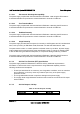
Table 25. Cable Lengths
From
Length
(mm)
To Connector
#
Number
of Pins
Description
Power Supply cover exit hole 850 P1 24 Baseboard Power Connector
Power Supply cover exit hole 350 P2 8 Processor 1 Power Connector
Power Supply cover exit hole 500 P3 8 Processor 2 Power Connector
Power Supply cover exit hole 350 P4 5 Power PSMI Connector
Power Supply cover exit hole 650 P5 6 PCIE Graphics card Power Connector
Power Supply cover exit hole 650 P6 6 PCIE Graphics card Power Connector
Power Supply cover exit hole 350 P9 4 Peripheral Power Connector
Extension 100 P10 4 Peripheral Power Connector
Power Supply cover exit hole 800 P11 4 Peripheral Power Connector
Extension 75 P12 4 Right-angle SATA Power Connector
Power Supply cover exit hole 800 P13 5 Right Angel SATA Power Connector
Extension 75 P14 5 SATA Power Signal Connector
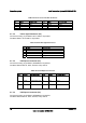
4.1.7 Power Connectors
4.1.7.1 Baseboard Power Connector (P1)
Connector housing: 24-pin Molex* Mini-Fit Jr.
39-01-2245 or equivalent
Contact: Molex* Mini-Fit, HCS, Female, Crimp 44476 or equivalent
Table 26. P1 Baseboard Power Connector
Pin Signal 18 AWG Color Pin Signal 18 AWG Color
1* +3.3 VDC Orange 13 +3.3 VDC* Orange
3.3V RS Orange (24AWG) 14 -12 VDC Blue
2 +3.3 VDC Orange 15 COM Black
3* COM Black 16 PSON# Green
4* +5 VDC Red 17 COM Black
5V RS Red (24AWG) 18 COM Black
5 COM Black 19 COM Black
6 +5 VDC Red 20 Reserved N.C.
7 COM Black 21 +5 VDC Red
8 PWR OK Gray 22 +5 VDC Red
9 5VSB Purple 23 +5 VDC Red
10 +12V3 Yellow 24 COM Black
+12V3 RS Yellow (24AWG)
11 +12V3 Yellow
12 +3.3 VDC Orange