
Technical Product Specification


Intel® Workstation System SC5650SCWS TPS Overview
Revision 1.2
Intel order number: E81822-002
9
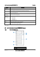
Callout Button / LED Name Color Condition Description
A Power LED Green
On Power on
Off Power off
B Power Button N/A N/A Powers the system on or off
C NMI Button N/A N/A
Used to force system halt and dump memory
contents to screen or file
D Reset Button N/A N/A Reboots and initializes the system
E NIC1 Activity
Green
On Linked
Blink LAN activity
Off Idle
F NIC2 Activity
Green
On Linked
Blink LAN activity
Off Idle
G Hard Drive Activity Green Blink Hard drive activity
H System Status LED
Green
On System booted and ready
Blink
System ready, but degraded: some CPU fault,
DIMM killed, and so forth
Amber
On
Critical alarm: Critical power module failure,
critical fan failure, voltage (power supply),
voltage, thermal fault, and so forth
Blink
Non-critical failure: Redundant fan failure,
redundant power failure, non-critical power
and voltage, and so forth
Off
Off AC Power off;
Off
Powered Down (DC-off state or S5), and no
degraded, non-critical, critical conditions
exist*
Figure 5. Front Panel Components
* When the workstation is powered down (transitions to the DC-off state or S5), the BMC is still
on standby power and retains the sensor and front panel status LED state established before
the power-down event. If the system status is normal when the system is powered down (the
LED is in a solid green state), the system status LED will be off.
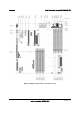
2.2.5 Mechanical Locks
2.2.6 Mechanical Locks
The Intel® Workstation System SC5650SCWS chassis support the installation of a padlock loop
(see letter “A” in the following figure) at the rear of the chassis. Additionally, the system ships
with a two-position mechanical lock (see letter “B”) on the front bezel assembly to prevent
access to the hard drives and the interior of the system.