
Technical Product Specification


Connector/Header Locations and Pin-outs Intel® Workstation System SC5650SCWS TPS
Revision 1.2
Intel order number: E81822-002
142
Pin Signal Name Description
9 TPA- TPA negative signal
10 TPA+ TPA positive signal
7.6 Audio Connectors
The workstation board provides one stacked audio connector on the back edge of the board
(J6A1). This stacked connector provides six jacks for audio connections (Back Surround Out,
Center/LFE Out, Front Surround Out, Line-in, Microphone in, and Side Surround Out).
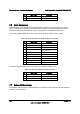
The following table details the pin out of the internal front panel audio header (J1D2).
Table 100. Internal Front Panel Audio Header Pin-out (J1D2)
Pin Signal Name Description
1 Port 2 L Audio Port 2 Left Channel
2 AGND_AUD Ground
3 Port 2 R Audio Port 2 Right Channel
4 Presence Detect Detect Presence of Front
Panel Audio Port
5 Port 1 R Audio Port 1 Right Channel
6 Port 2 Sense Return
7 AGND_AUD Ground
8 Key
9 Port 1 L Audio Port 1 Left Channel
10 Port 1 Sense Return
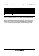
The following table details the pin out of the internal S/PDIF header (J4C1).
Table 101. Internal S/PDIF Header Pin-out (J4C1)
Pin Signal Name Description
1 PWR_P5V S/PDIF Power
2 AUD_SPDIF_OUT S/PDIF output
3 GND Ground
7.7 Onboard Video Header
The adapter cable accessory (FXXSCVDCBL) is required to convert the internal onboard video
header to a 15-pin D-Sub