
Technical Product Specification


Intel® Workstation System SC5650SCWS TPS Connector/Header Locations and Pin-outs
Revision 1.2
Intel order number: E81822-002
141
Pin Signal Name Description
6 NC Not Connect
7 Ground
8 NC Not Connect
9 Key No pin
10 LED# Activity LED
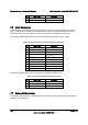
One additional Type A USB port (J1H2) is provided on the workstation board to support the
installation of a USB device inside the workstation chassis.
Table 97. Internal Type A USB Port Pin-out (J1H2)
Pin Signal Name Description
1 USB_OC USB_PWR
2 USB_ICH_P7N USB port 7 negative signal
3 USB_ICH_P7P USB port 7 positive signal
4 GND Ground
7.5.6 IEEE 1394a connectors
The following table details the pin-out of the external IEEE 1394a port (J8A2).
Table 98.External IEEE 1394a Port Pin-out (J8A2)
Pin Signal Name Description
1 Power 1394 Power
2 GND Ground
3 TPB- TPB negative signal
4 TPB+ TPB positive signal
5 TPA- TPA negative signal
6 TPA+
TPA positive signal
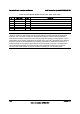
The following table details the pin-out of the internal 1394 connector (J1D2).
Table 99. Internal 1394 Port Pin-out (J1D2)
Pin Signal Name Description
1 GND Ground
2 Key
3 PWR 1394 Power
4 PWR 1394 Power
5 TPB- TPB negative signal
6 TPB+ TPB positive signal
7 GND Ground
8 GND Ground