
Technical Product Specification


Connector/Header Locations and Pin-outs Intel® Workstation System SC5650SCWS TPS
Revision 1.2
Intel order number: E81822-002
140
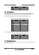
Two 2x5 connectors on the workstation board (J1D1, J1D4) provide support for four additional
USB ports.
Table 94. Internal USB Connector Pin-out (J1D1)
Pin Signal Name Description
1 USB2_VBUS4 USB power (port 4)
2 USB2_VBUS5 USB power (port 5)
3 USB_ICH_P4N_CONN USB port 4 negative signal
4 USB_ICH_P5N_CONN USB port 5 negative signal
5 USB_ICH_P4P_CONN USB port 4 positive signal
6 USB_ICH_P5P_CONN USB port 5 positive signal
7 Ground
8 Ground
9 Key No pin
10 TP_USB_ICH_NC Test point
Table 95. Internal USB Connector Pin-out (J1D4)
Pin Signal Name Description
1 USB2_VBUS6 USB power (port 6)
2 USB2_VBUS8 USB power (port 8)
3 USB_ICH_P6N_CONN USB port 6 negative signal
4 USB_ICH_P8N_CONN USB port 8 negative signal
5 USB_ICH_P6P_CONN USB port 6 positive signal
6 USB_ICH_P8P_CONN USB port 8 positive signal
7 Ground
8 Ground
9 Key No pin
10 TP_USB_ICH_NC Test point
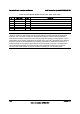
One low-profile 2x5 connector (J1D3) on the workstation board provides an option to support a
low-profile Solid State Drive.
Table 96. Pin-out of Internal USB Connector for Low-Profile Solid State Drive (J1D3)
Pin Signal Name Description
1 +5V USB power
2 NC Not Connect
3 USB Data - USB port 11 negative signal
4 NC Not Connect
5 USB Data + USB port 11 positive signal