
Technical Product Specification


Intel® Workstation System SC5650SCWS TPS Connector/Header Locations and Pin-outs
Revision 1.2
Intel order number: E81822-002
137
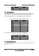
Pin Signal Name Description Pin Signal Name Description
17 BND (Reset GND) Reset Button
Ground
18 SMB_SENSOR_3V
3STB_CLK
SMB Sensor
Clock
19 FP_ID_BTN_N ID Button 20 FP_CHASSIS_INT
RU
Chassis
Intrusion
21 FM_SIO_TEMP_SENSO
R
Front Panel
Temperature
Sensor
22 NIC2_ACT_LED_N NIC 2 Activity
LED -
23 FP_NMI_BTN_N NMI Button 24 NIC2_LINK_LED_
N
NIC 2 Link LED -
7.5 I/O Connectors
7.5.1 NIC Connectors
The workstation board provides two stacked RJ-45 / 2xUSB connectors side-by-side on the
back edge of the board (JA5A1, JA6A2). The pin-out for NIC connectors is identical and defined
in the following table.
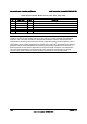
Table 88. RJ-45 10/100/1000 NIC Connector Pin-out (JA5A1, JA6A2)
Pin Signal Name
1 GND
2 P1V8_NIC
3 NIC_A_MDI3P
4 NIC_A_MDI3N
5 NIC_A_MDI2P
6 NIC_A_MDI2N
7 NIC_A_MDI1P
8 NIC_A_MDI1N
9 NIC_A_MDI0P
10 NIC_A_MDI0N
11 (D1) NIC_LINKA_1000_N (LED
12 (D2) NIC_LINKA_100_N (LED)
13 (D3) NIC_ACT_LED_N
14 NIC_LINK_LED_N
15 GND
16 GND
7.5.2 SATA Connectors
The workstation board provides up to six SATA connectors: SATA-0 (J1G5), SATA-1 (J1G4),
SATA-2 (J1G1), SATA-3 (J1F4), SATA-4 (J1F1), and SATA-5 (J1E3).
The pin configuration for each connector is identical and defined in the following table.