
Technical Product Specification


Connector/Header Locations and Pin-outs Intel® Workstation System SC5650SCWS TPS
Revision 1.2
Intel order number: E81822-002
136
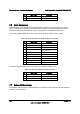
7.3.3 HSBP Header
Table 85. HSBP Header Pin-out (J1F5, J1G3)
Pin Signal Name Description
1 SMB_IPMB_5V_DAT BMC IMB 5V Data Line
2 GND Ground
3 SMB_IPMB_5V_CLK BMC IMB 5V Clock Line
4
P5V – HSBP_A
GND – HSBP_B
+5V for HSBP A
Ground for HSBP B
7.3.4 SGPIO Header
Table 86. SGPIO Header Pin-out (J1G2)
Pin Signal Name Description
1 SGPIO_CLOCK SGPIO Clock Signal
2 SGPIO_LOAD SGPIO Load Signal
3 SGPIO_DATAOUT0 SGPIO Data Out
4 SGPIO_DATAOUT1 SGPIO Data In
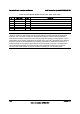
7.4 Front Panel Connector
The workstation board provides a 24-pin SSI front panel connector (J1B3) for use with Intel
®
and
third-party chassis. The following table provides the pin-out for this connector.
Table 87. Front Panel SSI Standard 24-pin Connector Pin-out (J1B3)
Pin Signal Name Description Pin Signal Name Description
1 P3V3_STBY
(Power_LED_Anode)
Power LED + 2 P3V3_STBY Front Panel
Power
3 Key No Connection 4 P5V_STBY (ID
LED Anode)
ID LED +
5 FP_PWR_LED_N Power LED - 6 FP_ID_LED_BUF_
N
ID LED -
7 P3V3
(HDD_ACTIVITY_Anode
)
HDD Activity
LED +
8 FP_LED_STATUS
_GREEN_N
Status LED
Green -
9 LED_HDD_ACTIVITY_N
HDD Activity
LED -
10 FP_LED_STATUS
_AMBER_N
Status LED
Amber -
11 FP_PWR_BTN_N Power Button 12 NIC1_ACT_LED_N NIC 1 Activity
LED -
13 GND (Power Button
GND)
Power Button
Ground
14 NIC1_LINK_LED_
N
NIC 1 Link LED -
15 BMC_RST_BTN_N Reset Button 16 SMB_SENSOR_3V
3STB_DATA
SMB Sensor
DATA