
Technical Product Specification


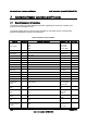


Connector/Header Locations and Pin-outs Intel® Workstation System SC5650SCWS TPS
Revision 1.2
Intel order number: E81822-002
134
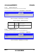
10 +12 Vdc Yellow 22 +5 Vdc Red
11 +12 Vdc Yellow 23 +5 Vdc Red
12 +3.3 Vdc Orange 24 GND Black
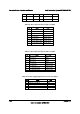
Table 80. CPU 1 Power Connector Pin-out (J9A1)
Pin Signal Color
1 GND of Pin 5 Black
2 GND of Pin 6 Black
3 GND of Pin 7 Black
4 GND of Pin 8 Black
5 +12 Vdc CPU1 Yellow / black
6 +12 Vdc CPU1 Yellow / black
7 +12 Vdc DDR3_CPU1 Yellow / black
8 +12 Vdc DDR3_CPU1 Yellow / black
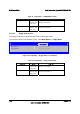
Table 81. CPU 2 Power Connector Pin-out (J9K1)
Pin Signal Color
1 GND of Pin 5 Black
2 GND of Pin 6 Black
3 GND of Pin 7 Black
4 GND of Pin 8 Black
5 +12 Vdc CPU2 Yellow / black
6 +12 Vdc CPU2 Yellow / black
7 +12 Vdc DDR3_CPU2 Yellow / black
8 +12 Vdc DDR3_CPU2 Yellow / black
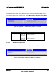
Table 82. Power Supply Signal Connector Pin-out (J9K2)
Pin Signal Color
1 SMB_CLK_FP_PWR_R Orange
2 SMB_DAT_FP_PWR_R Black
3 SMB_ALRT_3_ESB_R Red
4 3.3 V SENSE- Yellow
5 3.3 V SENSE+ Green