
Service Guide


Workstation Board Features
6 Intel® Workstation Board S5520SC Service Guide
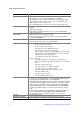
Jumper Name Pins What happens at system reset
from EFI-bootable recovery media with a recovery BIOS image present.
These pin should not be connected for normal system operation.
BMC Force
Update
(J1H1)
1-2 (Default) BMC Firmware Force Update Mode – Disabled.
These pins should have a jumper in place for normal system operation.
2-3 BMC Firmware Force Update Mode – Enabled.
These pins should not be connected for normal operation.
Serial Port A
Configuration
(J4B2)
1-2(Default)
Rear RJ-45 Serial A port is configured for DSR to DTR.
2-3 Rear RJ-45 Serial A port is configured for DCD to DTR.
Back Panel Features
A. POST Diagnostic LEDs G. Audio: side surround out
B. Serial A Port (top), IEEE 1394a port
(bottom)
H. Audio: front surround out
C. ID LED I. Audio: microphone in
D. System Status LED J. Audio: line-in
E.
Audio: back surround out K. NIC 1 (top, default management port), Two USB (bottom)
F.
Audio: center/LFE out L. NIC 2 (top), Two USB (bottom)
Figure 4. Back Panel Features
The NIC LEDs at the right and left of each NIC provide the following information.
Table 3. NIC LEDs
NIC LED Color LED State Description
NIC 1 and NIC 2
(Gigabit)
Left LED
Off No network connection
Blinking Green Transmit/receive activity
Right LED
Off 10 Mbps connection (if left LED is on or blinking)
Solid Green 100 Mbps connection
Solid Amber 1000 Mbps connection