
Service Guide


Intel
®
Server System SR1695WB Service Guide 33
Note: Do not touch the socket pins; they are very sensitive and easily damaged.
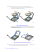
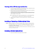
9. Align the processor cutouts to match the two socket pins, and then insert the
processor into the socket as shown in Figure 21.
Figure 21. Aligning the Processor
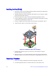
10. Close the load plate (see the letter “A” in Figure 22), close the socket lever and
ensure the load plate tab engages under the socket lever when fully closed. (See
letter “B” and “C” in Figure 22)
Figure 22. Close the Load Plate and Socket Lever
Note: Make sure the alignment triangle mark and the alignment triangle cutout align correctly.
To assist in package orientation and alignment with the socket:
AF003293
B
A
AF003294
C
B
A