
Hardware User's Guide

24 Intel® Integrated RAID Module RMS2MH080 Hardware User’s Guide
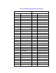
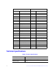
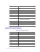
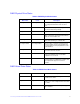
Fault Tolerance
Table 8. Fault Tolerance Features
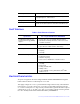
Electrical Characteristics
All power is supplied to the Intel
®
Integrated RAID Module RMS2MH080 through the
board-to-board connector via PCI Express* 3.3 V rails.
The supply voltages are 3.3 V ± 5 percent from PCI edge connector only. The maximum
power for the +3.3 V rail is 18 W. The +12 V rail is not provided by the base card. The
+3.3 V rail is used by the 3.3 V logic circuitry and also used to generate the other required
voltage rails of +1.0V, +1.2V, and +1.8 V. The +3.3 V auxiliary voltage is used to generate
the +12 V standby for the Intel
®
RAID Smart Battery AXXRSBBU7.
Flexibility Drive migration, RAID level migration, Drive Roaming, Online
Capacity Expansion - without reboot
Background services Rebuild, Consistency Check, Migration, OCE, and Patrol Read
Cache options Write-back or Write-through; Read Ahead, Adaptive Read
Ahead, Non Read Ahead; Cache I/O or Direct I/O; Disk Cache
Specification Intel
®
Integrated RAID Module RMS2MH080
Specification Intel
®
Integrated RAID Module RMS2MH080
Self Monitoring Analysis and
Reporting Technology (SMART)
support
• Detects up to 70% of predictable disk drive failures
• Monitors the internal performance of all motors, heads,
and drive electronics.
Optional Battery Backup • Intel
®
RAID Smart Battery AXXRSBBU7 cache backup
• Up to 48 hours of data retention, ‘Gas Gauge’
Drive Replacement • Auto detection of failure
• Hot-plug
• Hot-swap
Drive Rebuild Using Hot Spares • Automatic at fail
• Dedicated per Array
• Global for any array
• Auto-resume of initialization or rebuild on reboot
Error Checking and Indication • Parity generation and checking, automatic consistency
checking
• Patrol reads
• Activity and fault LEDs
• Multiple retries
• Logs in NVRAM, event log, CIM, Smart, Intel
®
RAID
Web Console 2