
Technical Product Specification

Intel® Server System SR1695WB TPS Configuration Jumpers
Revision 1.4
Intel order number: E92079-005
40
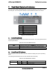
8.1 Force Integrated BMC Update (J1B5)
When performing a standard BMC firmware update procedure, the update utility places the
BMC into an update mode, allowing the firmware to load safely onto the flash device. In the
unlikely event the BMC firmware update process fails due to the BMC not being in the proper
update state, the server board provides a BMC Force Update jumper (J1B5) that forces the
BMC into the proper update state. You must complete the following procedure in the event
the standard BMC firmware update process fails.
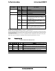
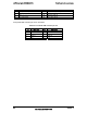
Table 47. Force Integrated BMC Update Jumper
Jumper Position Mode of Operation Note
1-2 Normal Integrated BMC GPIO [1] is pulled HIGH. Default position.
2-3 Update Integrated BMC GPIO [1] is pulled LOW.
1. Power down and remove the power cord.
2. Open the server chassis. Refer to your server chassis documentation for
instructions.
3. Move the jumper from the default operating position, covering pins 1 and 2, to the
enabled position, covering pins 2 and 3.
4. Close the server chassis.
5. Reconnect the power cord and power up the server.
6. Perform the BMC firmware update procedure as documented in the README.TXT
file included in the given BMC firmware update package. After the successful
completion of the firmware update process, the firmware update utility may
generate an error stating the BMC is still in update mode.
7. Power down and remove the power cord.
8. Open the server chassis.
9. Move the jumper from the enabled position, covering pins 2 and 3 to the disabled
position, covering pins 1 and 2.
10. Close the server chassis.
11. Reconnect the power cord and power up the server.
Note: Normal BMC functionality is disabled when the Force BMC Update jumper is set to the
enabled position. You should never run the server with the BMC Force Update jumper set in
this position. You should only use this jumper setting when the standard firmware update
process fails. This jumper should remain in the default/disabled position when the server is
running normally.
8.2 Password Clear (J1C2)
This 3-pin jumper is used to clear the BIOS password.
Table 48. BIOS Password Clear Jumper
Jumper Position Mode of Operation Note
1-2 Normal ICH10R INTRUDER# pin is pulled HIGH. Default position.
2-3 Clear Password ICH10R INTRUDER# pin is pulled LOW.
8.2.1 Clearing the BIOS Password
1. Power down server. Do not unplug the power cord.
2. Open the chassis. For instructions, refer to your server chassis documentation.
3. Move the jumper (J1B6) from the default operating position, covering pins 1 and 2,
to the password clear position, covering pins 2 and 3.
4. Close the server chassis.