
Technical Product Specification

Front Panel Control and Indicators Intel® Server System SR1695WB TPS
Revision 1.4 37
Intel order number: E92079-005
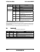
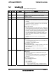
Notes:
1. The BIOS detects these conditions and sends a Set Fault Indication command to the Integrated BMC to
provide the contribution to the system status LED
2. Blink rate is ~ 1Hz at 50% duty cycle.
7.2.3 System Status LED – BMC Initialization
When power is first applied to the system and 5V-STBY is present, the BMC controller on
the server board requires 15-20 seconds to initialize. During this time, the system status LED
will be solid on, both amber and green. Once BMC initialization has completed, the status
LED will stay green solid on. If power button is pressed before BMC initialization completes,
the system will not boot to POST.
7.2.4 System Identification LED
The system ID LED provides a visual indication of a system being serviced. The state of the
system ID LED is affected by the following:
Toggled by the system ID button
Controlled by the Chassis Identify command (IPMI)
Controlled by the Chassis Identify LED command (OEM)
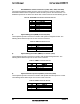
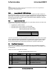
Table 44. System ID LED Indicator States
State LED State
Identify active via button Solid on
Identify active via command ~1 Hz blink
Off Off
There is no precedence or lock-out mechanism for the control sources. When a new request
arrives, all previous requests are terminated. For example, if the system ID LED is blinking
and the system ID button is pressed, then the system ID LED changes to solid on. If the
button is pressed again with no intervening commands, the system ID LED turns off.
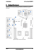
7.3 Front Panel Connectors
Front Panel uses 2 cables to connect with motherboard, one is 24-pin SSI control panel
cable to J1D3 on motherboard, another is 10-pin 2 ports USB cable to J9A2 (USB port 0/1)
on motherboard.
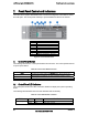
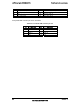
The pin-out for SSI control cable is as follows:
Table 45. Front Panel SSI connector pin-out
Pin Signal Name Pin Signal Name
1 P3V3_STBY (Power LED Anode) 2 P3V3_STBY (Front Panel Power)
3 Key 4 P5V_STBY (ID LED Anode)
5 FP_PWR_LED_N 6 FP_ID_LED_BUF_N
7 P3V3 (HDD Activity LED Anode) 8 FP_LED_STATUS_GREEN_N
9 LED_HDD_ACTIVITY_N 10 FP_LED_STATUS_A MBER_N
11 FP_PWR_BTN_N 12 NIC1_ACT_LED_N
13 GND (Power Button GND) 14 NIC1_LINK_LED_N
15 BMC_RST_BTN_N 16 SMB_SENSOR_3V3STB_DATA