
Technical Product Specification

Intel® Server System SR1695WB TPS Front Panel Control and Indicators
Revision 1.4
Intel order number: E92079-005
34
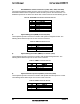
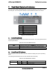
7. Front Panel Control and Indicators
The Intel
®
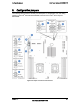
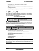
Server System SR1695WB Front Control Panel integrates control buttons, LEDs,
and USB ports. The control panel assembly is pre-assembled and fixed to the chassis.
A Power/Sleep Button
B System Reset Button
C Power/Sleep LED
D System NIC 1 Activity LED
E System NIC 2 Activity LED
F System Identification LED
G System Status LED
H System Identification Button
I USB 2.0 Connectors – Port 0/1
Figure 27. Front Control Panel
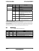
7.1 Control Panel Button
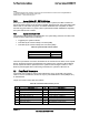
The following table lists the control panel features and functions. The control panels features
a system power button.
Table 40. Front Control Button Function
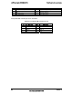
7.2 Control Panel LED Indicators
The control panel houses five LEDs, which are viewable to display the system’s operating
status.
The following table identifies each LED and describes their functionality.
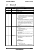
Table 41. Front LED Indicator Functions
LED Indicator Color Condition What it describes
Power/Sleep Green On Power On/ACPI S0 state
Green Blink Sleep /ACPI S1 state
Feature Function
Power/Sleep Button
Toggles the system power on/off. This button also functions as a
Sleep Button if enabled by an ACPI-compliant operating system.
System Reset Button Reset system to reboot
System ID Button Turn On/turn off ID LED